
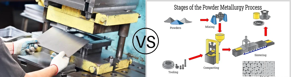
Image Source: AI GeneratedManufacturers must choose between powder forming and stamping to produce metal parts. Metal stamping cuts and shapes flat sheet metal that is typically less than 0.25″ thick, and it leaves scrap material behind. Powder metal processing, by contrast, compacts metal powder in dies and sinters it into solid components with approximately 97% material utilization.
Each method has distinct benefits in design flexibility and edge quality, along with production economics. This piece compares metal stamping and powder metallurgy by design capabilities, part quality, and cost considerations. It helps readers identify the metal stamping process or powder forming approach that best suits their manufacturing requirements.
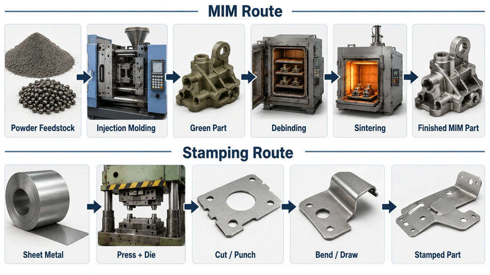
Stamping vs Powder Forming: How Each Process Makes a Part
Metal Stamping Process: Cutting, Piercing, and Forming Sheet Metal
Sheet metal stamping uses immense pressure on flat coils or blanks with specialized dies mounted in a press. The ram pushes the upper die, which contains the punch, downward toward the lower die block. This force shears, bends, or stretches the material into the required shape.
Blanking cuts a part’s complete outer profile from sheet stock and creates the flat blank that becomes the finished component. Piercing, often called perforating, creates holes by cutting through the material. The process discards the slug and retains the hole. Trimming removes a formed part’s outer perimeter to achieve its finished profile and creates scrap known as addendum or offal. Notching cuts the outer edges of strip material in progressive dies and creates the initial blank shape.
Forming operations permanently deform material without cutting it. Bending creates angles along straight lines, but engineers must account for springback, where the material partly returns to its original shape. Deep drawing creates seamless cup-shaped parts through controlled material flow. Embossing stretches material to form raised or recessed features, while coining compresses it under high pressure to achieve extreme dimensional accuracy and substantial thickness changes.
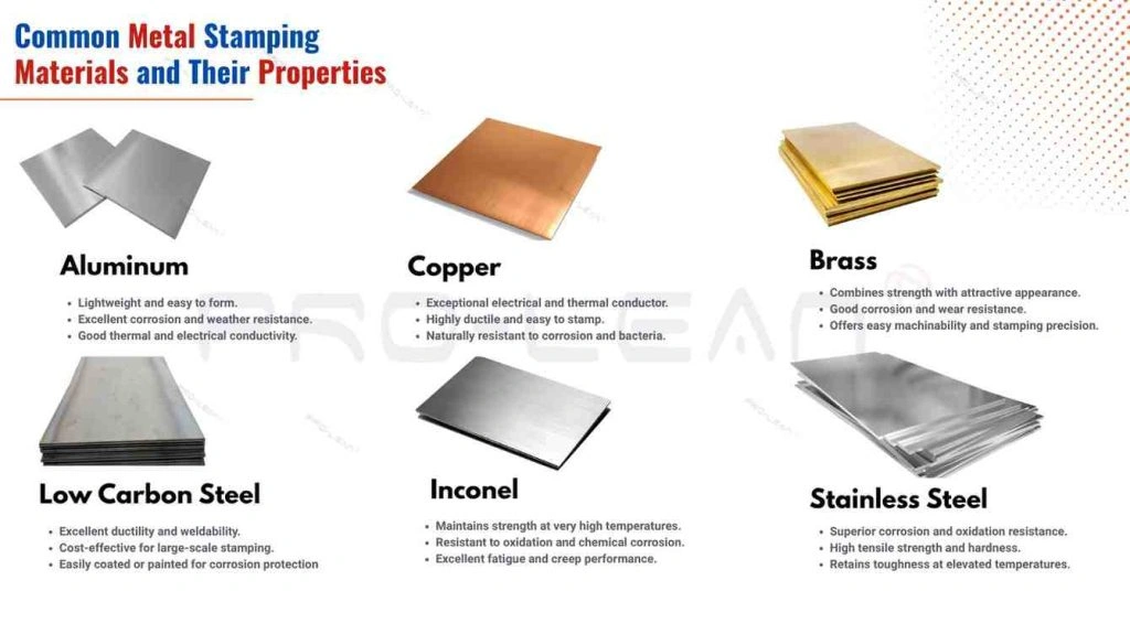
Stamping works with almost all sheet metal alloys, including cold-rolled steel, hot-rolled steel, stainless steel, aluminum, brass, and copper. It works best with thicknesses between 0.127 mm (0.005 in) and 6.35 mm (0.25 in). Once tooling is complete, a stamping press can produce dozens to hundreds of similar parts per minute and maintain tight dimensional consistency across millions of cycles.
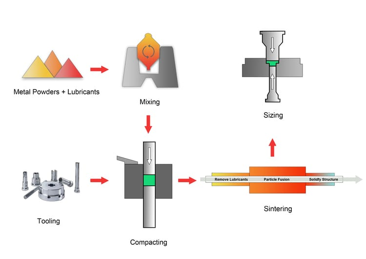
Powder Forming Process: Blending, Pressing, and High-Temperature Sintering
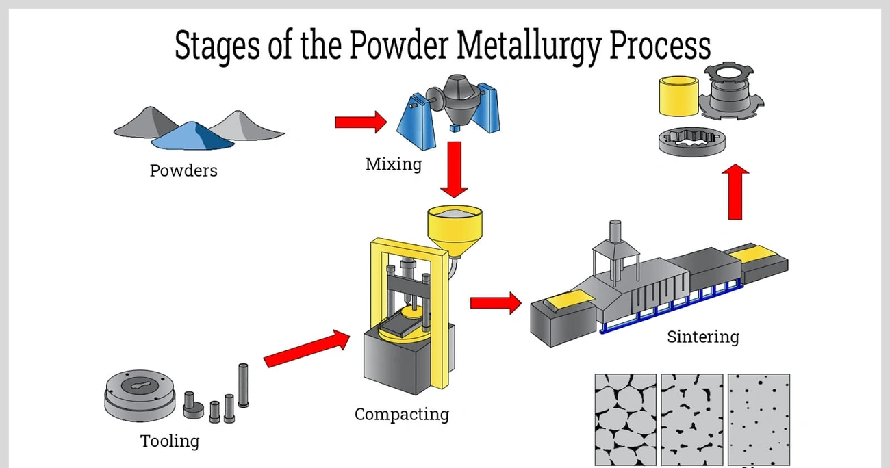
The powder metal process starts by mixing elemental or alloy powders with lubricants and additives to create a uniform mixture. Lubricants reduce friction during compaction because punch-to-die clearances typically measure less than 0.001 inches. Additives can improve the finished part’s machinability, wear resistance, or lubricity.
Compaction takes place in a die at pressures from 138 MPa (10 tsi) to 965 MPa (70 tsi), based on density requirements and powder compressibility. Most parts require pressing forces between 10,000 lbs/in² (70 MPa) and 120,000 lbs/in² (800 MPa). Double-action presses use opposing top and bottom punches to distribute compaction evenly throughout the powder. The resulting “green compact” needs enough structural integrity to withstand handling before sintering.
Sintering moves the green compact through a controlled-atmosphere furnace, where the part heats to temperatures below the base metal’s melting point. A nitrogen/hydrogen mix has been the preferred atmosphere for most sintering since the late 1970s. The furnace includes a pre-heat zone to burn off binders and lubricants, followed by a hot zone that raises parts to 70% to 90% of their melting point. A cooling zone then lowers the temperature gradually. This process creates metallurgical bonds between powder particles and gives the part its mechanical and physical properties.
Comparison Scope: Conventional Press-and-Sinter PM vs. Sheet Stamping
This analysis compares conventional press-and-sinter powder metallurgy with sheet metal stamping. Press-and-sinter processes produced about 93% of worldwide powder metallurgy industry output in 2019. Most conventional parts weigh less than 5 pounds (2.27 kg), while stamping operations usually process thin-to-medium sheet materials. Each method serves a distinct manufacturing niche based on part geometry, material properties, and production economics.
Part Design: Thin Sheet Shapes vs. Multi-Level Powder Metal Parts
Thin Walls and Complex Bends: Where Sheet Metal Stamping Fits Best
Sheet thickness determines whether a part suits stamping. Available gages range from 0.024 in. (0.609 mm) to 0.250 in. (6.35 mm), and the process keeps wall thickness uniform across the formed part. Flat parts can be as small as 0.250 in. x 0.250 in., while formed parts need minimum dimensions of 0.500 in. x 0.500 in.. Maximum part dimensions reach 39 in. x 47 in., with bend lengths up to 47 in..
Bends create springback, which occurs when the material partially returns to its original shape after forming pressure releases. Cold-rolled steel has 0.75 to 1.0 degree of springback, while 304 stainless steel has 2 to 3 degrees. Aluminum springback ranges from 1.5 to 2 degrees. Mild steel can spring back by as much as 30 degrees when the inside radius equals or exceeds eight times the material thickness. High-strength steels show about 25% more springback than residual differential strain models predict.
Steps, Hubs, and Integrated Bosses: Multi-Level Features Powder Metallurgy Can Form
The powder metal process produces multi-level geometries in one compaction stroke. Hubs that complement gears, sprockets, or cams form easily, although hub-to-flange sections need generous radii. Boss-forming cavities in punch tools cannot extend beyond 15% of the part height, and draft angles of at least 12° per side prevent the compact from sticking to the punches.
Wall thickness limits differ from stamping. Minimum wall thickness is 1.52 mm (0.060 in.). Length-to-wall-thickness ratios of 8:1 or greater need special precautions to ensure uniform die fill and result in unavoidable density variations. Most powdered metal gears range from 0.5 inches to 6 inches in diameter, with thicknesses up to 2 inches. Compaction can easily form blind or tapered holes, including blind steps. Side holes need post-sintering machining.
Part Size and Force Limits: Stamping Tonnage vs. Powder Press Capacity
Press capacity calculations determine feasibility. Powder compaction tonnage equals the projected surface area in square inches multiplied by the compaction pressure in pounds per square inch, then divided by 2,000. A part with 4 square inches of area that requires 40 tons per square inch needs at least 160 tons of force. Available hydraulic powder presses range from 15 tons to a maximum capacity of 800 tons.
Die Release and Geometry Rules: Sheet Springback vs. Powder Ejection Draft Angles
Stamping offsets springback through overbending, while powder forming avoids draft on part sides. Draft on outer sections helps with ejection but requires careful tool timing and reduces production rates. Undercuts perpendicular to the pressing direction prevent part ejection.
Part Combination: Assembled Stampings vs. One-Piece Sintered Components
Powder metallurgy can combine multi-part assemblies into single components. An appliance hinge that previously required three stamped stainless steel pieces that workers aligned and riveted became one powder metal part. This change removed assembly operations and improved structural strength. Hand tool manufacturers converted a three-part subassembly, which included a stamped sprocket, machined body, and fastener, into one multi-level powder metal component. The change saved about $1.00 per assembly. GE Aviation’s fuel nozzle combined 20 separate components into one part and reduced weight by 25%.
Part Quality: Tolerances, Edge Finish, and Material Properties
Dimensional Accuracy: Sheet Metal Springback vs. Sintering Shrinkage and Sizing
Tooling controls radial dimensions in powder metal parts. Modern CNC compaction presses monitor position and speed through feedback loops to maintain part-to-part precision. Sintered parts without secondary sizing achieve dimensional tolerances of ±0.3% to ±0.5% of the nominal dimension. A 20 mm feature maintains a tolerance range of ±0.06 mm to ±0.10 mm. Sizing operations tighten control to ±0.025 mm, while secondary machining handles requirements beyond this threshold. Stamping must account for springback after forming pressure releases, which complicates final dimensional control.
Working Edges: Sheared Stamping Edges vs. Pressed and Sintered Surfaces
Sheared stamping edges contain four distinct zones: rollover from plastic deformation, a burnish area where the blade creates a vertical rubbed edge, a fracture area with rough angular surfaces, and a burr caused by excessive clearance or dull tools. Cutting clearance, blade sharpness, material properties, and tool wear affect the edge configuration. Burr height increases as tools wear through repeated cutting cycles. Powder metal surfaces have smooth profiles with controlled porosity. Their surface finish compares favorably with ground or ground-and-polished wrought components.
Mechanical Strength and Wear: Wrought Sheet Steel vs. Density-Dependent Powder Metal
Powder metallurgy properties relate directly to final density, measured as mass per unit volume in g/cm³. Structural parts range from 80% to more than 95% relative density. Yield strength measures 62% to 98% of ultimate strength. This value is closer to tensile strength than in wrought metals. Elongation generally remains below 10% in ferrous materials because of porosity, although some stainless steels reach 15% to 25%. High-density Fe-2%Ni powder metal with less than 2% porosity shows fatigue endurance limits that rise with heat treatment, especially under hardened and tempered conditions.
Magnetic Properties: Electrical Steel Sheets vs. Tailored Powder Metal Blends
Powder metal materials F-0000, pure iron with <0.03% sintered carbon, and FY-4500 17Y, pure iron with 0.45% phosphorus, show higher permeability, lower coercivity, and higher induction at given applied fields than AISI 1008 stamping steel. These powder formulations provide faster magnetic response and better magnetic performance.
Powder Metallurgy vs. Metal Stamping Cost: From Tooling to Finished Parts
Tooling Costs: Progressive Stamping Dies vs. Powder Compaction Tool Sets
Progressive die costs range from $10,000 for small parts under 5 square inches to $200,000 or more for large, complex designs. Average tooling investment ranges from $35,000 to $60,000, while soft tooling options start at about $3,000 to verify a design. Standardized tooling with quick-change inserts can reduce lead times to 6-8 weeks. Most OEMs recover tooling costs within 6 to 18 months.
Material Yield: Sheet Nesting Scrap vs. 95%+ Near-Net Powder Utilization
Stamping leaves unused material in the sheet web, while the powder metal process achieves about 97% material utilization. Manufacturers can break apart and reuse green compacts when needed. Recycling sheet metal scrap recovers only part of the original material cost.
Secondary Operations: Deburring, Tapping, and Welding vs. Coining and Sizing
Sheared stamping edges require deburring as a standard secondary finishing operation. Complex stamped assemblies add fixture and welding costs, while most powder metal components need only one press operation and one tool set. Progressive dies can also include tapping stations.
Production Speed: Stamping Press Cycles vs. Powder Press and Furnace Throughput
Stamping presses operate from 25 to more than 200 strokes per minute. Small mechanical powder presses compact about 100 pieces per minute. Sintering furnace throughput adds cycle time after compaction.
Lead Time and Validation: Tool Build, Material Sourcing, and Part Qualification
Standard tooling production can finish within 6-8 weeks under certain conditions. Powder metallurgy material sourcing can take nearly a month before the required powder arrives in-house, and production may require additional weeks.
Break-Even Volume: Amortizing Tooling for Total Cost per Accepted Part
Break-even quantity calculation: (High Volume Tooling Cost − Low Volume Tooling Cost) ÷ (Low Volume Cost Per Part − High Volume Cost Per Part). A scenario with $2,000 in low-volume tooling and $20,000 in high-volume tooling, with costs of $5.00 and $1.00 per part, reaches break-even at 4,500 parts.
Choosing Stamping or Powder Metal for Your Application
Application Fit: Thin Brackets, Clips, and Panels vs. Gears, Cams, and Structural Hubs
Powder metallurgy dominates gear production throughout automotive applications. Synchronizer gears, oil pump gears, and engine gears show how the auto industry has shifted from wrought steel to powder steel. Some manufacturers use only PM gears for camshaft synchronization. Powder metal gears also appear outside automotive engines in household appliances, tractor transmissions, crane drives, and components such as balance shaft adjustors, motor-driven window lift and seat adjustors, cranking motors, distributors, and headlight activators. The process also suits power tools, motorcycles, and ATVs, where lightweight designs reduce inertia losses by 6-7 percent. Cams benefit from the surface finish and part-to-part consistency that powder forming provides.
Sheet metal stamping is suited to thin brackets, clips, electrical enclosures, and panels when uniform wall thickness and two-dimensional profiles meet functional requirements. Stampings also support applications that need large, flat surfaces with minimal depth.
Supplier Evaluation: Sample Prototyping, CMM Verification, and Capacity Audits
Prototyping confirms design assumptions before companies invest in full production tooling. Coordinate measuring machine verification confirms dimensional accuracy against engineering specifications. Capacity audits determine whether a supplier’s press tonnage, furnace throughput, and quality systems can support projected volumes and delivery schedules.
Comparison Table
Comparison Table: Stamping vs Powder Forming
| Attribute | Metal Stamping | Powder Forming (Powder Metallurgy) |
|---|---|---|
| Process Description | Cuts and shapes flat sheet metal with dies and presses. The material is sheared, bent, or stretched. | Metal powder is compacted in dies under high pressure, then sintered at high temperature to create solid components. |
| Material Thickness Range | 0.127 mm to 6.35 mm (0.005 in. to 0.25 in.) | Minimum wall thickness: 1.52 mm (0.060 in.) |
| Part Size Range | Flat parts: 0.250 in. x 0.250 in. minimum. Formed parts: 0.500 in. x 0.500 in. minimum. Maximum: 39 in. x 47 in. | Most parts weigh less than 5 pounds (2.27 kg). Gears are typically 0.5 to 6 inches in diameter and up to 2 inches thick. |
| Material Utilization | Leaves scrap material, known as web, that can be recycled at a fraction of the original cost. | Uses about 97% of the material. Green compacts can be broken apart and reused. |
| Dimensional Tolerances | Springback affects tolerances by 0.75 to 30 degrees, depending on the material and bend radius. | Without sizing: ±0.3% to ±0.5% of the nominal dimension. With sizing: ±0.025 mm. |
| Edge Quality | Creates four zones: rollover, burnish, fracture, and burr. Deburring is required. | Produces smooth profiles with controlled porosity that match ground or ground-and-polished wrought components. |
| Multi-Level Features | Limited. Maintains uniform wall thickness throughout the part. | Excellent. Creates steps, hubs, integrated bosses, and blind holes in one compaction stroke. |
| Part Consolidation | Often requires multiple stamped pieces to be assembled with fasteners or welding. | Can combine multiple components into a single part, such as reducing a 3-part assembly to 1 part or 20 components to 1. |
| Tooling Costs | Progressive dies: $10,000 to $200,000+. Average: $35,000 to $60,000. Soft tooling: about $3,000. | Costs are not explicitly stated, but compaction tool sets are required. |
| Production Speed | 25 to 200+ strokes per minute, producing dozens to hundreds of parts per minute. | Small mechanical presses produce about 100 pieces per minute, plus sintering furnace time. |
| Press Capacity | Measured in tonnage and varies by press size. | Hydraulic presses have a maximum capacity of 15 to 800 tons. |
| Typical Applications | Thin brackets, clips, electrical enclosures, panels, and large flat surfaces with minimal depth. | Gears, cams, structural hubs, synchronizer gears, oil pump gears, and power tool components. |
| Secondary Operations | Requires deburring and may need tapping, welding, or assembly. | Most parts need one press operation and one tool set. Sizing or machining may be needed for tight tolerances. |
| Mechanical Properties | Delivers full wrought-metal properties. | Yield strength: 62% to 98% of ultimate strength. Elongation is generally below 10% for ferrous materials because of porosity. |
| Density | 100% solid wrought metal. | 80% to above 95% relative density for structural parts. |
| Magnetic Properties | Standard electrical steel properties (AISI 1008). | Specific formulations, such as F-0000 and FY-4500 17Y, provide superior magnetic performance with higher permeability and lower coercivity. |
| Design Limitations | Requires springback compensation and uniform thickness. Undercuts perpendicular to the forming direction are not possible. | Side holes require post-sintering machining. Bosses need draft angles of at least 12°, and length-to-wall-thickness ratios above 8:1 may cause concerns. |
| Tooling Lead Time | 6–8 weeks with standardized tooling. | Material sourcing takes about 1 month, plus additional weeks for production. |
| Suitable Materials | Cold-rolled steel, hot-rolled steel, stainless steel, aluminum, brass, and copper. | Elemental or alloy powders, including pure iron, iron-nickel, iron-phosphorus, and stainless steels. |
| Industry Adoption | Commonly used for sheet metal components. | Press-and-sinter processes produced about 93% of worldwide PM industry output in 2019. |
Conclusion
Stamping provides fast cycle times and strong performance for thin brackets, clips, and flat panels when the design calls for uniform wall thickness. Powder metallurgy works well when multi-part assemblies need to become single components, especially gears, cams, and structural hubs with multi-level features.
Material utilization favors powder forming at 97%, while stamping generates scrap. Tooling costs and production volumes determine each process’s economic viability.
Manufacturers should review part geometry and density requirements first. They should then consider production quantities. Designs with walls thinner than 1.52 mm often suit stamping, while components that need integrated bosses or steps favor powder metallurgy. Manufacturers can test prototypes with both methods to determine which process produces better results for specific applications.
FAQs
Q1. How does metal stamping make parts?
Metal stamping uses a press and dies to cut, bend, or stretch sheet metal into a desired shape. It suits high-volume production of thin parts such as brackets, clips, and panels.
Q2. What is powder metallurgy, and how does it work?
Powder metallurgy makes parts by blending metal powders, pressing them into a die, and heating them below the base metal’s melting point. This heating step, called sintering, bonds the particles together.
Q3. Which operations are commonly used in metal stamping?
Common operations include blanking, piercing, trimming, notching, bending, deep drawing, embossing, and coining. The combination depends on the part’s shape; there is no single sequence required for every part.
Q4. What advantages does powder forming offer over stamping?
Powder forming uses about 97% of its material and can combine multiple components into one part. It also forms features such as steps, hubs, and bosses, potentially reducing assembly and machining.
Q5. How do I choose between stamping and powder forming?
Choose stamping for thin, uniform-wall parts with bends or large flat surfaces. Consider powder forming for gears, cams, and hubs with multiple levels. Compare strength requirements, tooling costs, production volume, and finishing needs before deciding.