
Powder Metallurgy Press: Comparing Mechanical, Hydraulic, and Electric Systems for Manufacturing
What is a Powder Compacting Press?
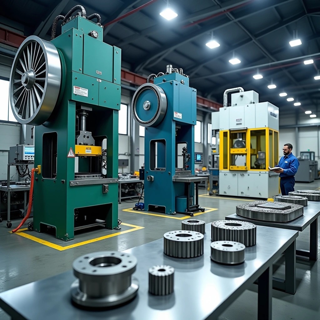
A powder compacting press applies controlled force to metallic, ceramic, polymer, or other powder materials within a rigid die to produce dense, near-net-shape components. The equipment transforms loose powder into coherent green compacts through precise control of three critical parameters: fill depth, compaction force, and ejection timing. This forming process achieves uniform density and dimensional consistency in parts that range from aerospace components to automotive gears.
Press configurations vary based on application requirements. Single-action systems compress powder from one direction and are suitable for thin, flat geometries. Multi-action designs employ independent control of cavity depth, compaction force, and part ejection to maintain uniform density throughout complex shapes. Upper and lower punches coordinate with programmable force curves in these systems. This eliminates voids and minimizes springback during ejection.
The Role of High-Pressure Compaction in Density Uniformity
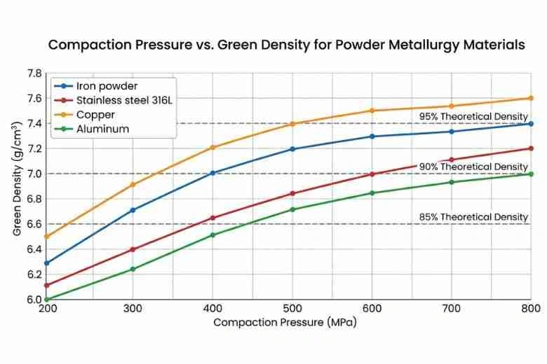
Compaction pressure determines green density and final part performance directly. Standard industrial applications operate within 150 MPa to 700 MPa. Specialized processes can reach pressures up to 2,500 MPa. Die filling and compaction control the uniformity of green density in powder compacts. This parameter determines dimensional accuracy after sintering.
Higher pressures reduce inter-particle cavity size and variability more than low-pressure compaction does. Pressure increases beyond 500 MPa activate multiple densification mechanisms. Plastic deformation of individual particles and cold welding at contact points are two such mechanisms. Research demonstrates that high-pressure compaction improves functional properties of iron-based soft magnetic powder materials by a lot. The pressure-density relationship remains non-linear and material-specific. Each powder system needs careful calibration.
Mechanical Powder Press Technology
Operating Mechanism and High-Speed Drive Systems
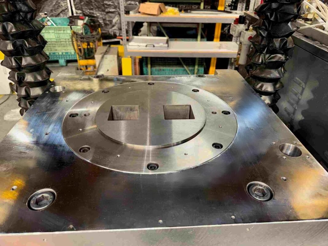
Mechanical powder metallurgy press systems convert rotational motion from an electric motor into linear pressing force through mechanical linkages such as eccentric cams, cranks, or toggle mechanisms. The motor drives a flywheel that stores energy in rotational form and transmits it through a gear train to the crankshaft. This crankshaft moves the press slide vertically and translates stored energy into a defined, repetitive linear stroke of the ram. The mechanical transmission from motor-driven flywheel to ram makes production rates reach up to 6,000 strokes per hour, with modern systems achieving 1,500 strokes per minute.
Advantages for High-Volume, High-Output Part Manufacturing
Speed defines the main value of mechanical powder pressing machines in mass production environments. These systems deliver 30 to 50 parts per minute and prove efficient when manufacturing simple to moderately complex components. The fixed cycle operation will give unmatched repeatability, with dimensional tolerances controlled within ±0.05mm. Energy consumption per cycle remains lower than hydraulic alternatives during operation, though flywheel startup requires higher energy at the start. The simpler mechanical design reduces maintenance requirements and lowers operating costs per part for high-volume production runs.
Structural Limitations and Geometry Constraints
Force delivery peaks at the bottom of the stroke and restricts optimal performance to processes that need precise deformation at specific points. Maximum compaction forces for mechanical powder presses reach 5,000 kN or greater, with force output fixed by mechanism design. Stroke control flexibility remains limited compared to hydraulic systems. This makes these presses better suited for shallower parts with consistent geometries. Short stroke lengths restrict applications with compressible powders, while uniaxial pressing often produces density gradients in parts with high height-to-diameter ratios.
Hydraulic Powder Compacting Presses
Fluid System Pressure Generation for Heavy-Duty Compaction
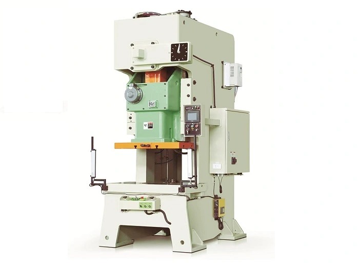
Hydraulic powder compacting presses generate force through fluid-filled cylinders: a ram cylinder and a smaller plunger cylinder. Force applied to the plunger pressurizes the hydraulic fluid and distributes pressure to expand the ram cylinder. This fluid power transmission delivers full programmed force at any point in the ram’s stroke, which differs from mechanical systems that peak force delivery at stroke bottom. Operators achieve fine adjustments to pressure, dwell time and ram speed throughout each cycle. This enables precise control for compacting materials from soft metal powders to dense, hard alloys.
Advantages for Multi-Level and Tall Parts Production
Multi-level components that require stepped features or varying wall thicknesses benefit from independent control of upper punch, lower punch and floating die movement. The system synchronizes each axis with micron-level precision and ensures uniform density across all levels. This capability is needed for producing synchronizer hubs and valve components. Hydraulic presses maintain stable compaction force from stroke start to finish, which ensures that each powder layer compresses uniformly. Tonnage configurations range from 15 to 1,200 tons for single or multi-level parts.
Large-Scale Sintered Gear and Rotor Application Scenarios
Hydraulic compaction produces gears, sprockets and brackets that require precise tolerances and high durability. The process compacts titanium and stainless steel powders for aerospace and medical implant components where uniformity and biocompatibility remain critical. Controlled pressure profiles minimize porosity and enhance structural strength with dimensional accuracy.
Advanced Electric Servo Press Systems
Servo Motor Drive Technology & Micro-Precision Control
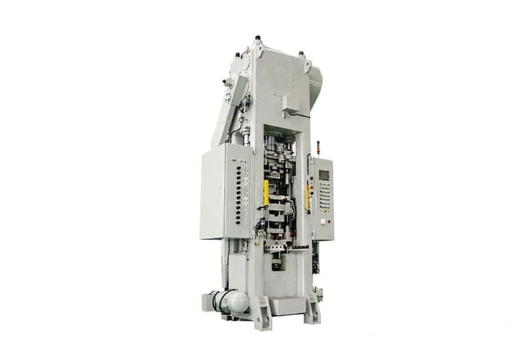
Electric servo powder metallurgy press systems replace hydraulic cylinders with brushless AC servo motors coupled to ball screws or planetary roller screws. The motor connects through a gearbox to linear actuators that deliver pressing force. Control systems coordinate operation through precision programmed motion profiles. Servo drives run cascaded position-velocity-current control loops at update rates of 4 kHz or faster. This makes independent control over force and speed possible at every stroke point, along with position control. Positioning accuracy reaches ±0.01 mm, with force repeatability within ±0.5% of full scale. Single actuator configurations deliver up to 50 tons of force, while powder metallurgy equipment pressing forces extend to 700 kN.
Eliminating Green Part Micro-Cracks via Programmed Ejection Speed
Servo-electric powder pressing machines operating on the ejection principle allow punches to float freely during compaction without fixed stops. This makes pressure relief possible in both axial directions and compensates for punch compression and springback effect to ensure crack-free demolding. Programmable motion profiles control ejection velocity between 5 and 20 mm per second through forming zones. Shock loading decreases and tool life extends from 50,000 hits to over 200,000 cycles.
Energy Efficiency and Complex Core-Rod Control Benefits
Servo systems consume energy only during pressing cycles. Continuous pump operation is no longer needed. Energy savings reach 80% compared to pneumatic or hydraulic alternatives, with consumption up to 70% lower than hydraulic presses. Independent servo-electric drive control for all pressing and filling axes makes synchronized multi-level compaction possible with micron-level precision across complex core-rod geometries.
Critical PM Press Performance Parameters
Max Pressing Force & Ejection Force Requirements
Selection of powder metallurgy equipment begins with evaluating maximum tonnage capacity against part geometry and material requirements. Pressing force determines achievable green density. Ejection force must overcome friction between compacted powder and die walls. Iron-based powders require 400 to 800 MPa compaction pressure. This translates to tonnage calculations based on projected part area. Ejection force specifications range from 10% to 30% of pressing force and vary with part complexity and powder lubrication.
Max Filling Height and Core Rod Travel Tolerances
Fill depth capacity defines the maximum uncompacted powder volume a compacting press can accommodate. Presses specify maximum fill heights from 50 mm for small-capacity machines to 300 mm for industrial systems. Core rod travel distance determines the complexity of internal features possible in pressed components. Multi-level parts with internal cavities require synchronized core rod movement. Travel tolerances are held within ±0.02 mm to prevent tool collision.
Positioning Accuracy and Linear Stroke Controls
Positioning precision affects dimensional consistency in finished parts. Modern powder pressing machines achieve punch positioning accuracy between ±0.01 mm and ±0.05 mm. Linear stroke control maintains constant ram velocity throughout compaction cycles, especially critical for preventing lamination defects in tall parts. Stroke programmability allows customized compression profiles for different powder formulations.
Our Factory Compaction Infrastructure
Tonnage Portfolio: From 5-Ton Micro-Presses up to 1,000-Ton Heavy-Duty Machinery
JHMIM brings more than 20 years of deep expertise in powder metallurgy and metal injection molding (MIM). We operate an 18,000+ square meter manufacturing facility in China. Our team of 150+ skilled technicians and advanced high-tonnage sintering and pressing equipment deliver high-density, zero-defect complex metal components worldwide. Our compacting press infrastructure spans tonnage capacities from 5-ton micro-presses for precision laboratory work up to 1,000-ton heavy-duty machinery for large-scale industrial parts. Mid-range hydraulic powder compacting presses cover 15 to 800 tons. CNC-controlled systems maintain accuracy within 0.001 inch. Standard powder metallurgy equipment ranges from 4 to 1,600 tf across mechanical, hydraulic, and servo-electric configurations. Servo-electric systems work well up to 500 tons where precise fill, compaction, and ejection control remain critical.
Strict Equipment Maintenance for Lifetime Tooling Protection
Preventive maintenance protocols safeguard high-value powder pressing machine tooling against premature wear and catastrophic failure. Routine inspection intervals track punch length, tip wear, and die bore condition. This identifies degradation patterns before they compromise production. Surface treatments and appropriate coatings extend tool life from 50,000 to over 200,000 cycles by minimizing friction and preventing galling. Structured maintenance records document each service action and create institutional knowledge that optimizes intervals and prevents recurring failures.
Maximize Efficacy: Optimize Your Part Design for Our Press Line
Submit Your 3D Drawings (STEP/IGS) for a Free Press Feasibility & DFM Analysis
You can share CAD files at the concept stage and get early DFM feedback before you finalize part designs. Submit 3D models in STEP or IGES format among 2D drawings that specify critical dimensions and tolerances. Annual production volume estimates should be included with functional requirements such as strength and hardness specifications and cost targets to assess feasibility accurately.
The engineering team assesses component geometry during evaluation. They look at surface area, wall thickness, material properties, compaction ratios, required levels and secondary operations. This assessment identifies opportunities to improve manufacturability and maintain performance objectives. Multi-disciplined engineers create solid models adjusted for dimensional changes and build parametric press stack-ups to visualize tooling. They generate individual tool drawings with materials and tolerances specified along with finishes. The team recommends optimal powder blends that deliver required mechanical properties for specific applications.
JHMIM operates a state-of-the-art 18,000+ square meter manufacturing facility in China with over 20 years of expertise in powder metallurgy and metal injection molding (MIM). We deliver high-density, zero-defect complex metal components globally. Our facility is backed by 150+ skilled technicians and advanced high-tonnage sintering and pressing equipment. We streamline your supply chain and solve tight-tolerance manufacturing challenges under one roof.