Understanding the Powder Metallurgy Process: Steps, Benefits, and Real-World Applications
Definition and Simple Principles of PM Technology
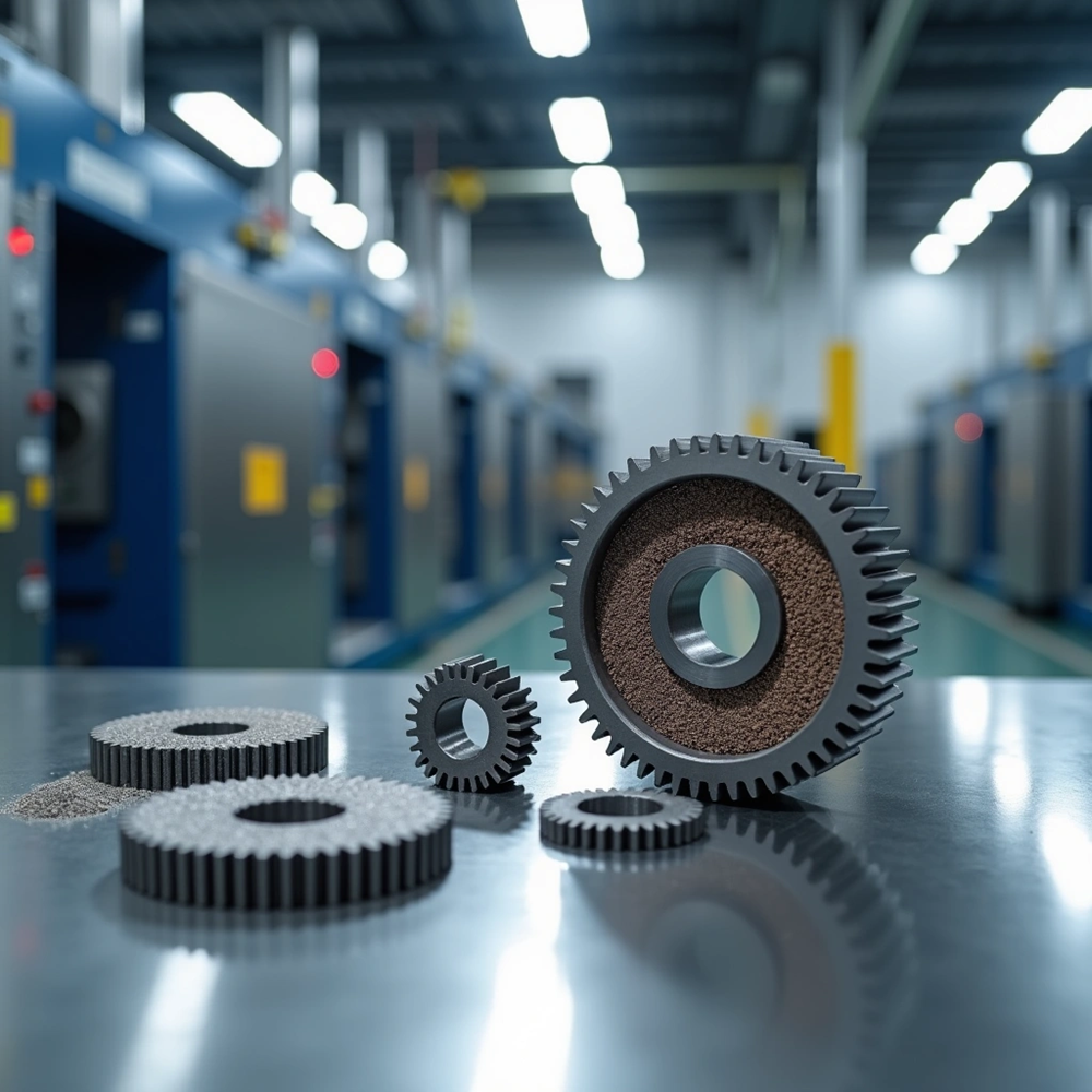
Powder metallurgy is a metal-forming process performed by heating compacted metal powders to just below their melting points. The powder metallurgy process involves placing metal powder in a mold and compacting it under high pressure to form an initial shape, then heating the compacted part below the melting point to enable solid-state diffusion between particles. This press-and-sinter methodology creates strong metallic bonds while reducing internal porosity. Particle bonding and recrystallization increase the part’s density and strength.
The powder metallurgy manufacturing process uses elemental or pre-alloyed powders that are blended and compacted in precision dies at room temperature. Sintering in controlled furnace atmospheres bonds the particles. High temperature helps atomic movement between particles and forms strong connections that provide mechanical properties suitable for demanding applications. The process achieves material utilization rates exceeding 97% of the starting raw material in finished parts, making PM a recognized green technology in metal manufacturing.
Net-Shape Manufacturing: Engineering Cost-Savings Over Traditional CNC
The powder metallurgy sintering process produces parts at or close to final dimensions. This reduces the need for subtractive machining operations. The near-net-shape approach provides efficiency gains. CNC machining creates approximately 50% material waste through chip removal, while PM achieves just 3% scrap rates. Production speed is different, with PM generating 1,800 parts per hour compared to CNC’s 20-60 parts.
Energy consumption patterns work better for PM, requiring 5.0 kWh/kg versus CNC’s 8.4-11.4 kWh/kg. The powder metallurgy process uses only the exact amount of material the design requires due to its additive nature. Parts emerge from dies already shaped to specifications. This accelerates time to market and maintains dimensional consistency across production runs without costly finishing steps.
The 4-Step Production Timeline
Step 1: Material Preparation & Fully Automated Powder Blending
Metal powders (elemental or pre-alloyed) are mixed with lubricants and binders in specific proportions to begin production. Automated blending systems ensure consistent homogenous blends and high throughput. They also evaluate product degradation and heat build-up concerns. Continuous powder blending measures, loads, blends and discharges materials at the same time. This reduces labor costs compared to traditional batch operations.
Step 2: High-Pressure Compaction (With 1,000-Ton Hydraulic Presses)
Hydraulic presses compress powders into green compacts. Press capacity ranges from 30 tons to 5,000 tons. Magnetic applications require pressures between 1,200 to 1,800 MPa to achieve desired densities, while stainless steels use 650 or 750 MPa. The hydraulic system provides precise and sustained pressure. This reduces powder volume, eliminates voids and locks particles into coherent shapes ready for sintering.
Step 3: High-Temperature Controlled Atmosphere Sintering
Sintering furnaces operate at 1,120°C/2,048°F for conventional processing. High-temperature variants exceed 1,200°C/2,200°F. The process has delubing (400-1,200°F), oxide reduction and sintering above 2,000°F where particles bond through solid-state diffusion. Nitrogen acts as cover gas while hydrogen reduces oxides. This prevents contamination during the 30-minute sintering cycle in N2/H2=90/10 atmospheres.
Step 4: Cooling Phase & Protective Dissociation Atmosphere Discharge
Controlled cooling rates between 0.5-5°C/s determine final microstructure and mechanical properties. Water quenching from sintering temperature prevents brittle precipitate formation in stainless steels. Slower cooling optimizes properties for specific applications under protective atmosphere layers.
Post-Sintering Secondary Operations
Most sintered components undergo finishing operations to meet exact specifications. These secondary processes refine dimensional accuracy, improve surface properties and optimize functional performance.
Hydraulic Sizing & Coining for Lock-In Tolerances ±0.005mm
Sizing involves repressing sintered parts in precision dies to correct dimensional variations from thermal changes. This operation achieves tolerances as tight as ±0.025 mm, with some applications reaching ±0.005mm through hydraulic sizing. The process increases density and smooths surface irregularities while sealing oil-impregnated bearing surfaces.
Controlled Steam Treatment (Creating Micro-Dense Fe3O4 Rust-Proof Layer)
Steam treatment exposes iron-based parts to superheated water vapor at 500-570°C for 1-2 hours. This forms a protective magnetite (Fe₃O₄) layer. This 5-7 micron oxide film achieves HRC 50 surface hardness and improves corrosion resistance, wear properties and compressive strength. The magnetite penetrates surface-connected pores and seals them, which enhances lubricant retention.
High-Vacuum Oil Impregnation for Self-Lubricating Bushings & Bearings
Vacuum impregnation fills component pores with lubricating oil under pressurized conditions. Self-lubricating bushings release oil during operation and reduce friction while lowering maintenance requirements. This process prevents moisture infiltration and extends service life in bearing applications.
Multi-Axis CNC Turning, Milling, and Precision Profile Grinding
Machining operations include turning and milling to achieve tight tolerances and surface finishes. JHMIM has over 20 years of deep expertise in powder metallurgy and metal injection molding (MIM). We operate a state-of-the-art 18,000+ square meter manufacturing facility in China. Backed by 150+ skilled technicians and advanced high-tonnage sintering and pressing equipment, we deliver high-density, zero-defect complex metal components globally.
Material Reference Portfolio
Sintered Metal Materials Matrix (Iron-Based, Copper Steel, Stainless Steel SS-316L)
Material selection determines performance outcomes in the powder metallurgy manufacturing process. Iron-based alloys dominate structural applications where strength and cost efficiency come together. These materials respond well to secondary treatments and deliver reliable mechanical properties in automotive and industrial sectors. Copper steel compositions add conductivity and thermal management capabilities. This makes them suitable for electrical components and heat-transfer applications. Stainless steel SS-316L offers superior corrosion resistance for medical devices, food processing equipment and marine environments where rust prevention remains critical.
In-House Tungsten Carbide Mold Infrastructure to Compensate Sintering Shrinkage
Tungsten carbide tooling withstands repeated high-pressure compaction cycles and retains dimensional accuracy. Parts shrink during sintering as particles bond and density increases. This requires precise die design to compensate for these dimensional changes. JHMIM has over 20 years of expertise in powder metallurgy and metal injection molding. The company operates an 18,000+ square meter manufacturing facility in China. It’s backed by 150+ skilled technicians and advanced high-tonnage sintering equipment. JHMIM delivers high-density, zero-defect complex metal components globally and streamlines supply chains by solving tight-tolerance manufacturing challenges under one roof.
High-Performance Target Industries
Automotive Systems (High-Strength Timing Gears, Flanges, and Pump Rotors)
Automobiles contain over 1,000 powder metallurgy parts. Sintered components weigh 13 to 45 kg per vehicle. The powder metallurgy process produces oil pump rotors that circulate engine lubricant to reduce friction and remove heat. Timing gears mounted on crankshafts ensure precise synchronization between crankshaft and camshaft rotation. Planetary gears in automatic transmissions enable smooth acceleration. Synchronizer cone rings improve gear shifting and reduce wear. Gerotor pump elements achieve 85-95% volumetric efficiency at pressures up to 200 bar.
Humanoid Robotics & Automation (Micro-Transmission Gears & Joint Actuators)
Metal injection molding fabricates micro gears with 1mm diameter and height for humanoid dexterous hands. Joint actuators account for more than 30% of a humanoid robot’s bill-of-materials cost. Full-sized robots need over 28 rotary and linear actuators. These components need high torque density, low backlash and compact integration of motor, gear and encoder assemblies. Humanoid robots take about 5,000 steps per hour. Leg actuators experience 2-3× body weight impacts per cycle.
Industrial Hardware, Power Tools, & Heavy-Duty Spindles
Power tool applications employ spur gears, helical gears and planetary gears for compact power transmission. Self-lubricating bearings operate in reciprocating saws and angle grinders. The powder metallurgy manufacturing process delivers gears with DIN class 8 quality and Ra 1.2 µm surface roughness.
Process Comparison & Design Constraints
Core Advantages: ≥95% Raw Material Utilization & Zero Scrap Overhead
The powder metallurgy process achieves material utilization exceeding 95%, with some operations reaching 97% efficiency. Traditional machining generates up to 50% waste through cutting operations. PM maintains only 3% scrap rates and outperforms conventional methods substantially. The powder metallurgy manufacturing process produces 30-50% less CO2 than conventional melting and machining techniques. Raw material conservation is just one benefit. Near-net-shape production eliminates excessive material removal and reduces environmental effects from mining and refining operations.
Design Limitations: Overcoming Undercuts and Vertical Draft Angles to Achieve Flawless Ejection
Metal powders exhibit limited lateral flow due to inter-particle friction. This restricts certain contour geometries. Undercuts on horizontal planes perpendicular to the pressing direction cannot be formed because they prevent part ejection from the die. Annular grooves and corner reliefs require secondary machining operations. Draft angles are unnecessary in the powder metallurgy process due to straight compaction and ejection. Slight draft on outer surfaces can aid release without slowing production rates. Wall thickness should not fall below 0.060 inch (1.52mm). This ensures consistent powder flow and die fill. Long, narrow walls may cause density variation and stress tooling components.
Powder Metallurgy Applications:Powder Metallurgy is used in many industries including automotive, aerospace, electronics, healthcare, energy and more.Some notable applications include:

Powder metallurgy is used extensively in the automotive industry to manufacture various components such as gears, bearings, valve seat inserts and camshafts. These components feature excellent wear resistance, high strength and dimensional stability, making them ideal for demanding automotive applications.
In the aerospace industry, powder metallurgy is used to manufacture complex shaped components such as turbine blades, structural parts and heat shields.This process enables the production of lightweight, efficient parts with complex designs, ensuring optimal performance and durability.

Powder metallurgy plays a key role in the manufacture of electrical contacts, magnetic components and electrical connectors for various electronic devices. The precise control of alloy composition and the ability to incorporate insulating materials into components make powder metallurgy an excellent choice for electrical applications.

The healthcare industry uses powder metallurgy to manufacture medical implants, dental components and surgical instruments. Powder metallurgy enables the production of biocompatible materials with excellent mechanical properties, ensuring safety and durability in medical applications.
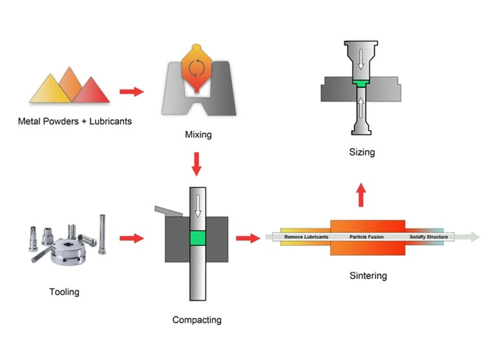
The powder metallurgy process consists of four primary steps: material preparation and automated powder blending, high-pressure compaction using hydraulic presses (ranging from 30 to 5,000 tons), high-temperature controlled atmosphere sintering at temperatures around 1,120°C, and a controlled cooling phase under protective atmosphere. Many parts also undergo post-sintering secondary operations like sizing, steam treatment, or machining to achieve final specifications.
Powder metallurgy offers exceptional material utilization exceeding 95%, compared to traditional CNC machining which generates approximately 50% waste. The process produces parts at near-net-shape, minimizing costly finishing operations, and consumes significantly less energy (5.0 kWh/kg versus CNC’s 8.4-11.4 kWh/kg). Additionally, PM achieves production rates of up to 1,800 parts per hour while maintaining only 3% scrap rates and producing 30-50% less CO2 than conventional melting and machining techniques.
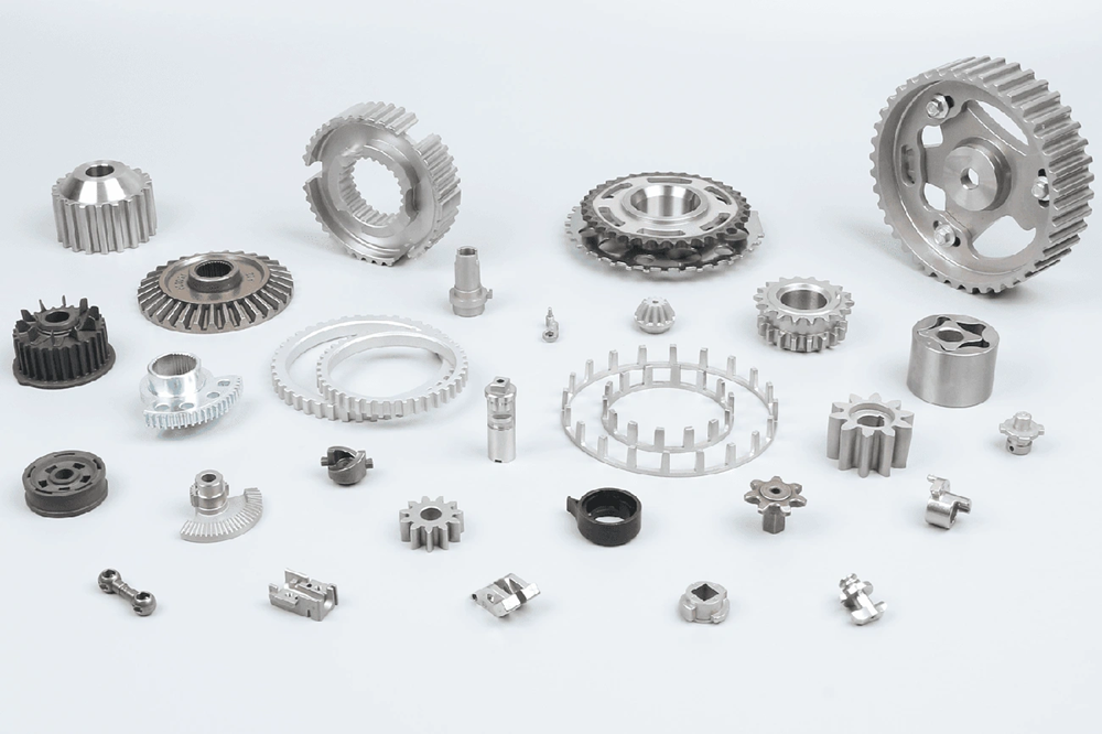
Powder metallurgy serves multiple high-performance industries including automotive systems (timing gears, oil pump rotors, planetary gears, and synchronizer rings), humanoid robotics and automation (micro-transmission gears and joint actuators), aerospace, medical equipment, and industrial hardware including power tools and heavy-duty spindles. Modern automobiles alone contain over 1,000 powder metallurgy parts weighing 13 to 45 kg per vehicle.
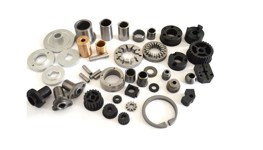
The powder metallurgy process works with various materials including iron-based alloys for structural applications, copper steel compositions for electrical and thermal management components, and stainless steel SS-316L for applications requiring superior corrosion resistance such as medical devices, food processing equipment, and marine environments. The process uses elemental or pre-alloyed powders that are blended, compacted, and sintered to achieve desired properties.
The main design constraints include the inability to form undercuts on horizontal planes perpendicular to the pressing direction, as these prevent part ejection from the die. Wall thickness should not fall below 1.52mm (0.060 inch) to ensure consistent powder flow and die fill. Annular grooves and corner reliefs require secondary machining operations. However, draft angles are generally unnecessary due to the straight compaction and ejection process, though slight draft on outer surfaces can facilitate release.
Start Your PM Project With Us
Upload Your 3D CAD Drawings (STEP/IGS) for an Expert Engineering & Tooling Review
Proper CAD file preparation is essential when you move from concept to manufactured component. STEP and IGES formats preserve solid geometry and maintain compatibility across software systems. These formats enable accurate manufacturability assessment before tooling investment begins. A 3D CAD model allows engineering teams to review geometric feasibility and identify possible design flaws while changes remain inexpensive to implement.
Design reviews serve as structured checkpoints. Cross-functional teams pressure-test ideas and confirm that designs meet functional, performance and compliance requirements. CAD models for powder metallurgy components undergo automated reconstruction to review pressing direction, wall thickness uniformity and ejection constraints. This preparation identifies features outside normal fabrication procedures before materials are ordered or dies are cut.
Mold design requires compensation for expansion during demolding and shrinkage during sintering. So tungsten carbide tooling must account for these dimensional changes to deliver finished parts within specified tolerances. Tooling size tolerance can reach ±0.002mm with surface finish of Ra0.2-0.4μm.
JHMIM has deep expertise in powder metallurgy and metal injection molding (MIM) spanning over 20 years. We operate a state-of-the-art 18,000+ square meter manufacturing facility in China. Our team of 150+ skilled technicians and advanced high-tonnage sintering and pressing equipment deliver high-density, zero-defect complex metal components globally. We streamline your supply chain by solving tight-tolerance manufacturing challenges under one roof.