
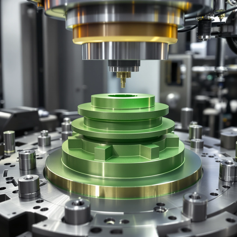
Multi-Level Powder Metallurgy Parts may look efficient on a drawing, but one poorly supported level can make ejection a costly point of crack risk.
Then die-wall friction, uneven pressure transmission, and springback can cause distortion or failure before sintering. This powder metallurgy design guide helps manufacturers improve powder metallurgy part manufacturing through powder compaction DFM and practical powder metal part design rules. It also covers controlled multi-level powder pressing. Powder selection and lubrication can reduce powder metallurgy density gradients in complex metal powder parts. Punch motion and pressure release must also align with the ejection sequence to limit these density variations.
Understand Why Multi-Level PM Parts Develop Defects
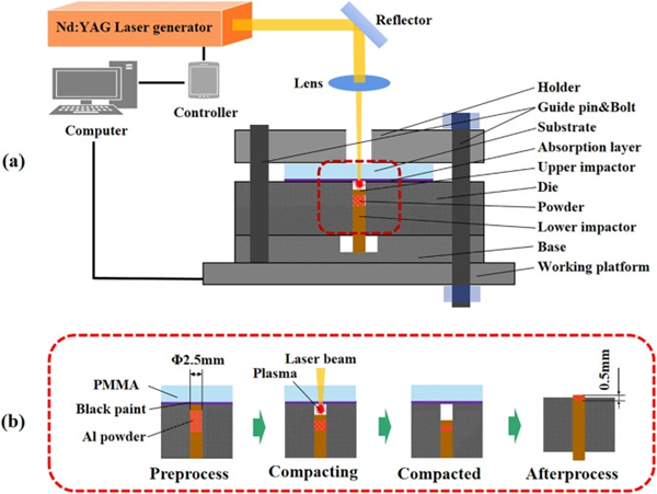
A multi-level compact faces different loading and release conditions at each height. Powder near a punch, beside a die wall, or under a thin flange does not respond like powder in a broad, well-supported section. Defect prevention starts by tracing how force enters, moves through, and leaves the powder mass.
How die-wall friction creates powder metallurgy density gradients
Metal powder does not behave hydraulically during compaction. Particle-to-particle friction and die-wall contact resist movement, so pressing force declines as it travels away from the punch. Powder closest to the load receives greater pressure, while powder farther along a tall wall, narrow section, or deep level receives less. This creates powder metallurgy density gradients before the compact reaches the sintering furnace.
Multi-Level Powder Metallurgy Parts intensify this effect because each level has a different fill height, wall-contact area, and pressure-transfer path. A thick hub connected to a thin flange, to cite an instance, can compact unevenly even if the press reaches its programmed total force. The compact may leave the die with one dense, strong region while another remains more porous and vulnerable during handling or ejection.
Die-wall friction also affects the force needed to remove the green compact. Residual radial pressure holds the compact against the die after unloading, and friction resists its initial movement. High-velocity compaction tests on an iron-based alloy showed that die-wall lubrication reduced ejection force by about 26% to 36% at the same impact velocity. That study also reported green-density gains of roughly 0.07 to 0.12 g/cm³ with die-wall lubrication. These figures do not set a universal production target because powder, geometry, and press action vary, but they show why friction control is central to powder compaction DFM.
Friction also changes where density develops. Powder along a long sliding surface loses more transmitted pressure than powder in a short, open section. A design review should then identify likely low-density zones before tooling release: deep walls, narrow annular features, long thin sections, and transitions between substantially different cross-sectional areas. A density map must follow the part’s geometry instead of relying on an average density from the whole component.
Why springback and weak green strength cause ejection cracks
The compact stores elastic energy under pressure. The powder mass expands axially and radially after the upper load releases. This elastic recovery, called springback, changes contact pressure against the die wall and can create tensile stress at fragile locations.
Springback rarely occurs evenly across a multi-level shape. A dense, thick level and a lower-density thin level recover differently. The part can bend around a step, flange junction, or thin wall if a punch withdraws or the die moves while one section remains restrained. The crack may begin as a small green-state separation and remain hard to detect before sintering.
Green strength determines whether the compact survives this stress. Mechanical interlocking and bonding between pressed powder particles create green strength. Low local density produces fewer or weaker particle contacts. The section then cannot carry the tensile and shear forces generated during unloading and ejection. Research on warm-die compaction identifies tensile stress during ejection, improper tool motion, and poor tooling surface condition as the main causes of green cracks.
Lubrication affects both sides of this problem. Too little lubricant raises die-wall friction and ejection force. Excess lubricant occupies volume within the powder mix and can reduce particle contact. The right amount supports powder movement and ejection while retaining enough green strength. One warm-die study achieved green strengths above 13 MPa under the tested conditions, and its optimized lubricant system reduced ejection pressures by 30% to 50% compared with the referenced standard lubricant.
Set practical limits rather than assume zero density variation
A powder metallurgy design guide should define an allowable density range by location and function. Zero variation is not a realistic planning basis for multi-level powder pressing because geometry, friction, elastic recovery, and powder flow create local differences. The design team should set limits that protect the most highly loaded region and the most fragile ejection feature.
- Identify critical zones. Mark thin walls, deep sections, flange roots, sharp level transitions, and long die-contact surfaces. These areas need local density and crack inspection instead of an average-part measurement.
- Set measurable acceptance criteria. Green density, dimensional change after unloading, ejection-force traces, hardness, and metallographic sections can reveal variation. Powder metallurgy inspection commonly has dimensional evaluation, density measurement, hardness testing, mechanical testing, and nondestructive methods.
- Link the limit to part function. A low-density cosmetic region and a low-density load path do not need the same tolerance. A section with little service load may still need a higher green-strength target if it supports the part during ejection.
Practical limits should also account for the geometry’s manufacturable range. PM guidance recommends walls no thinner than 1.52 mm as a general die-fill rule, while long thin walls can develop density variation. Length-to-wall-thickness ratios of 8:1 or higher require special precautions, and density variation remains unavoidable. These constraints give powder metal part design rules a measurable basis before the next stage reviews pressing direction, radii, and section transitions.
Apply Powder Metal Part Design Rules to Each Level
Geometry decisions determine whether every tool member can form, release, and support each level throughout its full stroke. For Multi-Level Powder Metallurgy Parts, a functional shape must also give punches, core rods, and the green compact a clear path. A powder metallurgy design guide should review every level as both part geometry and a moving tooling system.
Choose a pressing axis that allows tool withdrawal
Select one primary pressing and ejection axis before defining steps, bores, flanges, or grooves. Every surface that contacts the die, punches, and core rods must allow straight withdrawal along that axis. Undercuts, reverse tapers, re-entrant grooves, and lateral holes can block the compact or tool member during ejection, so they need a secondary operation after sintering.
Keep holes, keyways, splines, and similar internal profiles parallel to the pressing axis where possible. Core rods can form these features if the rods remain straight enough under compaction load. A long, slender core rod can deflect, shift the bore location, and cause ejection interference.
To name just one example, a stepped gear hub may be pressed vertically with its bore and gear axis arranged with punch motion. A radial mounting hole cannot follow that motion, so powder metallurgy part manufacturing must machine it later. This choice prevents the design from relying on tool movements the press cannot provide.
Check thin walls, deep sections, and unsupported flanges
Each level needs enough section thickness to allow filling and compaction, and it must remain intact without support during ejection. As a general rule, PM walls should not be thinner than 1.52 mm, or 0.060 in.. Long, thin walls also require fragile tooling and often create local density variation. If the length-to-wall-thickness ratio reaches 8:1 or more, the process needs special filling measures, although some variation remains unavoidable.
Review the following features level by level:
- Thin annular walls and deep bores: Confirm that powder can reach the full depth and that the core rod can withstand compaction load without bending.
- Flanges and overhangs: Keep flange steps small. A large flange can catch on the die or bend after it loses die-wall support. Add a generous radius at the flange root and lower edge.
- Bosses and deep punch cavities: Keep boss depth modest relative to the overall part height. A deep cavity can retain the compact on the punch and increase withdrawal force.
A part may meet its final service-load requirement but still fail this green-state geometry review. So powder compaction DFM must assess ejection support, not only strength after sintering.
Use radii and tapers at sharp section changes
Abrupt level changes concentrate stress as the compact recovers after pressing. Replace sharp internal intersections between hubs, webs, and flanges with radii so the compact receives support through the transition. Generous filets also improve tool life and reduce localized powder wedging.
External edges need a controlled chamfer with a small flat instead of a feather edge. A 30° to 45° chamfer with a 0.13 to 0.38 mm flat removes the fragile edge that can burr or break during ejection. Tooling guidance also identifies a 0.13 mm minimum radius or flat as preferable to a sharp edge.
Tapers can help tool withdrawal on difficult outer sections, although they require coordinated tool timing and may reduce production rate. Use them only if a straight wall creates a sticking risk. Either option must preserve support until the level clears the die.
Allow for sintering shrinkage and final tolerances
Sintering changes dimensions, and tool dimensions must account for that change. Powder composition, green density, sintering conditions, and geometry affect the result. Unequal density between levels can cause unequal shrinkage, so a tightly controlled bore or flange face should not sit beside a thin section with poor support.
Specify close tolerances only where function requires them. Ferrous pressed-and-sintered components typically allow practical tolerances of ±0.130 mm for press-held length and ±0.050 mm for inside or outside diameter. Dimensions perpendicular to the pressing direction are easier to control because the die constrains them during compaction. If the required tolerance exceeds stable as-sintered capability, the drawing should identify sizing, restriking, or machining as the planned finishing route.
This approach connects powder metal part design rules to measurable outcomes before multi level powder pressing moves into fill and punch-travel planning.
Select Powder and Lubrication for Consistent Compaction
Material selection defines the operating window for multi-level powder pressing once the geometry has passed screening. A powder mix must fill each level consistently, densify under the available load, and retain enough green strength for tool movement and handling. These properties interact, so improving one can weaken another. The powder metallurgy design guide should qualify the full mix rather than the base powder alone.
Balance powder flow, compressibility, and green strength
Begin with the powder characteristics that control filling. Particle size, size distribution, shape, and purity affect powder behavior, compactability, and final part properties. A mix that flows consistently helps achieve repeatable fill mass at every level. Free-flowing feed does not guarantee even compaction in narrow sections, though. Testing should use the intended feed shoe, cavity, and fill sequence.
Compressibility shows how well powder gains density as pressure increases. Internal friction restricts this response, while lubricant can reduce that resistance. Added lubricant takes up volume at higher pressing pressures and can reduce compressibility because its density is much lower than the metal’s. Green strength needs separate evaluation because it determines whether each level retains its edges and interfaces after compaction. Lubricants reduce green strength to different degrees.
Powder metallurgy part manufacturing should compare flow time, apparent density, pressure-density behavior, green strength, and ejection traces across candidate mixes using the actual part geometry. One iron-based study found that reducing a composite lubricant addition from 0.8% to 0.6% reduced ejection energy at high compaction pressure and increased density. This result does not provide a universal recipe, but it shows why every multi-level component needs its own trials.
Compare admixed lubricants with die-wall lubrication
Admixed lubricant blends throughout the powder and reduces friction between particles and against die walls. This established method supports pressing and ejection, but it becomes part of each fill volume. Its amount and chemistry therefore affect flow, green density, green strength, pore structure, and lubricant removal during sintering. Coarser lubricant particles can improve lubrication but may leave larger pores in the sintered component. Fine lubricants can limit pore size but may slow powder flow.
Die-wall lubrication separates the ejection function from much of the powder volume. A controlled thin coating on cavity walls reduces wall friction and allows the mix to use less admixed lubricant. A two-level warm-compaction example used 0.3% internal lubricant with die-wall lubrication instead of 0.6% lubricant in an admixed condition. Less internal lubricant can increase green density and strength, while the wall coating reduces ejection force and tool wear. Uniform coverage is especially important on long walls, deep cavities, and stepped surfaces.
Choose die-wall lubrication if the press applies a repeatable coating to each relevant surface and verifies coverage during production. Otherwise, select an admixed system with stable flow, compaction curves, green-strength results, and ejection traces. Select the system that delivers consistent local behavior at every level rather than the one with the highest average density during trials.
Plan Die Filling and Independent Punch Control
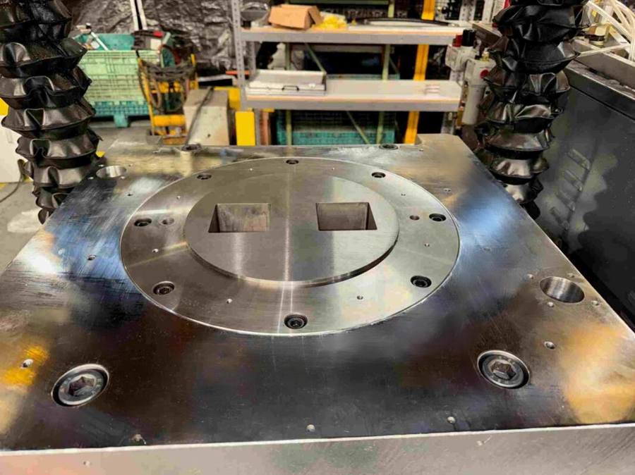
Tooling converts the selected powder blend into a repeatable compact. For Multi-Level Powder Metallurgy Parts, the fill position, individual punch strokes, and die motion must produce the intended powder mass at every height before compaction begins. Then, powder compaction DFM should document the full position sequence, not just the finished part dimensions.
Calculate fill height and compression ratio for each level
Calculate each level from its own cavity volume instead of applying one nominal fill height to the entire part. The loose powder height must provide the required mass after compression. Account for apparent density, target green density, and volume displaced by punches and core rods.
Use the compression ratio:
Compression ratio = loose fill height ÷ final compact height
Most metal powders use a compression ratio of about 2:1 to 3:1, but trials with the selected material and target density must establish the actual ratio. A deep hub and shallow flange may therefore need different fill depths and punch positions, even though they are part of one compact.
- Calculate the cavity volume for each level at the fill position.
- Subtract the volume occupied by punch faces and core rods.
- Convert the remaining volume into powder mass using measured apparent density.
- Set lower-punch and die positions to provide the required fill height. Then verify compact mass and local green density during trials.
Raising total compaction force cannot reliably correct inadequate fill at one level. This condition usually creates a local mass deficit rather than only reducing average density. An intermediate punch may, to cite an instance, establish a shelf during filling so powder fills an annular step before the final pressing stroke.
Check powder access to narrow die sections
Powder must enter narrow, deep, or partially enclosed regions before punch travel closes access. Get into the feed-shoe path, cavity opening, core-rod position, and level geometry together. Metal powder parts fill through gravity, force feeding, or both, and performance depends on how well the powder behavior matches the feed arrangement.
Determine whether powder can reach the narrowest region within the available fill time and whether displaced air can escape. Low permeability can cause intermittent flow because air moves slowly through the powder bed. Filling trials showed that materials with higher permeability achieved more complete fill, while poorly permeable powders had lower fill ratios as shoe speed increased.
Use transparent trial tooling, interrupted fills, or sectioned green compacts to check mass distribution in narrow annuli and deep pockets. Record shoe speed and powder condition for each trial. A blend that fills a broad test cavity may not reach a restricted level in production tooling.
Match punch count and travel to the press
Define each required motion before selecting a press or finalizing tooling. Multi-level powder pressing may require independent lower and upper punches, a floating die, and movable or fixed core rods. The press must provide enough controlled axes, travel, fill height, and force for every cycle position.
A press quotation should identify individual axis ratings, tooling motion diagrams, synchronization scope, and confirmed tooling interfaces instead of nominal tonnage alone. Engineers can then confirm whether a punch can remain stationary, move during compaction, or travel during withdrawal ejection without exceeding its available stroke.
Gasbarre multi-action presses, to cite an instance, provide three independently adjustable lower-punch platens and selective withdrawal ejection. Any lower-punch platen can act as the stationary level. This capability supports complex tooling only if the required sequence matches the installed press.
Avoid stepped tooling that removes support during ejection
Plan ejection while defining punch levels. A stepped tool can form the required shape but may create a crack if withdrawal removes support from a flange, web, or thin level while another section remains restrained in the die.
Specify which punch or die surface supports each level at every withdrawal position. Keep contact beneath fragile features until die-wall restraint decreases and the compact can move without bending. Avoid bridging tools just to compensate for an unsupported sequence if selective ejection can maintain a stable level. Record punch displacement, die displacement, and ejection force together during trials so measured behavior can guide tooling-sequence adjustments.
Set Pressing Conditions to Reduce Density Variation
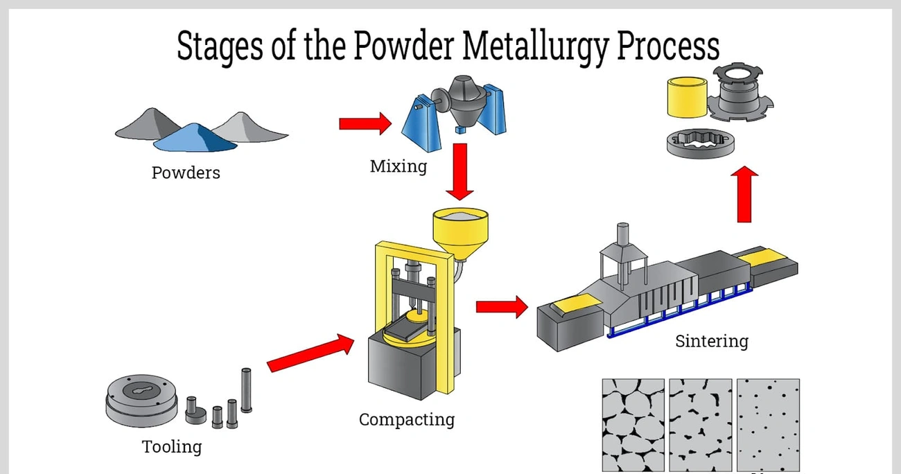
Adjust press settings to create local densification. Multi-Level Powder Metallurgy Parts cannot rely on one total-tonnage setting to confirm that every level reaches its required green density. Record force and punch displacement, along with in-die position, throughout the cycle. Compare results by level instead of relying on average part density.
Use measured pressure-density curves to choose compaction pressure
Build pressure-density curves with the selected powder mix under representative tooling conditions. Measure green density at several pressures and record in-die density during loading and density after unloading. The difference shows how elastic recovery changes the compact after pressure removal.
Loose metal powders often contain about 65% to 75% porosity. Pressures of 50,000 psi or more can reduce porosity in many powders to 20% or less, although results depend on the powder grade and pressing arrangement. Required pressure should come from measured behavior rather than a nominal press rating.
Review each curve’s slope. A rising density response shows that additional pressure still provides useful densification. A flattened response means higher force adds little density while increasing stored elastic energy and tool loading. Warm-die trials showed that a suitable material and lubricant combination increased green density by 0.05 to 0.07 g/cm³ in complex production-type shapes, rather than the 0.10 g/cm³ achieved under ideal simple-shape conditions.
Balance punch motion across levels
Coordinate upper and lower punch travel so each level receives pressure from the direction and distance needed for its fill height. One level should not reach its final position early and act as a rigid stop while a neighboring level continues to densify. This sequence transfers load unevenly through the compact and increases powder metallurgy density gradients.
Set the original punch positions from measured fill mass, then use trial compacts to adjust individual motion. Compare local density at the center, near die walls, and across step transitions. Inspect punch-force traces for abrupt load redistribution as well. A sudden change often shows that one punch reached its programmed stop before the remaining powder regions compacted as intended.
Warm-die studies show that density gains depend on pressure and lubricant level. At low pressure, a mix with too little lubricant can retain high particle-to-particle friction and produce lower density. At higher pressure, the same mix can densify more effectively. Therefore, multi-level powder pressing should treat force and punch travel as one controlled condition.
Provide time and clearance for trapped air to escape
Air must leave the powder bed before closing pores restrict its route to the punch-die clearance. Use a controlled precompression stage and a loading rate and clearance that allow air to escape during punch entry. Precompression removes air before the main load creates a dense outer region.
Controlled powder-compaction testing showed that precompression reduced elastic recovery from about 14% to about 4% at a 350 MPa main pressure. Even a 5 MPa precompression reduced recovery in that study. Powder metallurgy part manufacturing must confirm the comparable setting with the selected powder, cavity depth, and press speed. Monitor displacement during loading and unloading because a rising recovery signal can identify trapped air before metal powder parts develop hidden separations.
Control Pressure Release Before Ejection
Pressure must decrease in a sequence that keeps stress balanced across all punch contacts before the compact moves. Powder and tooling recover elastically during unloading, but their recovery amounts and rates differ. Multi-level powder pressing involves a lower punch, upper punch, core rod, and die, each of which can release stored energy differently. These differences alter restraint before the compact moves.
Compensate for unequal elastic recovery of the punches
Unequal recovery can place the green compact under tension or shear at an inner flange corner or a thin rim, even after the pressing load ends. Finite-element studies of multi-step shapes showed that uneven tool recovery creates differences in principal strain and concentrates shear stress during release and ejection.
The tooling team should program decompression as a motion profile rather than a single return command. The team should determine which punch supports each level, measure displacement as pressure is removed, and synchronize return strokes so adjacent levels unload with compatible axial movement. A lower punch beneath a rim should not recover before the punch or die surface restraining that rim. Holding one tool member for too long can also lock a locally expanding section against the die.
Instrumented trials should compare force and displacement throughout unloading. A smooth force decrease and aligned punch movement indicate stable release. Force reversals, sudden displacement changes, or increasing separation between punch positions indicate a mismatch. The team should repeat this check after tooling temperature changes because lubricant behavior affects elastic recovery.
Warm-die testing at 60°C reduced green expansion compared with standard compaction, while the behavior changed as die temperature reached 95°C and the lubricant approached melting. The tooling sequence should begin withdrawing die support from the compact only after the release is matched.
Design an Ejection Sequence That Keeps the Part Supported
Multi-Level Powder Metallurgy Parts require powder metallurgy part manufacturing to preserve support until each level clears the die after decompression.
Keep suitable hold-down force as the die withdraws
Hold-down load stays on the compact and prevents unsupported die motion. A published multi-step ejection case managed to keep 10 tons of hold-down force during die motion. Trial force traces set the load so friction drops without lifting a flange.
Coordinate core-rod and lower-punch movements
Core rods retract only after their surrounding walls have axial support. Lower-punch rise must align with core-rod withdrawal because either member can drag a bore, rim, or stepped web if movement starts too early. Record every member’s position at the first part movement.
Prevent bending as flanges leave the die
The flange root needs support from below while the die passes its outer edge. The free flange can recover while its hub remains constrained, which causes bending at the transition. Generous root radii help, but motion timing provides direct protection.
Set ejection speed with force and displacement data
Force and displacement curves determine ejection speed. Use slower movement through the highest-force interval and increase speed after wall contact declines. This powder compaction DFM approach protects metal powder parts during release.
Validate the Design With Simulation and Press Trials
Model the full cycle with measured material and friction data
Model filling, compaction, decompression, and ejection. Adjust the powder law using compression tests. Enter measured wall friction, original fill density, punch paths, and tool stiffness. Predict relative-density contours, springback, residual stress, and punch load.
Compare local stress with density-dependent green strength
Compare calculated tensile and shear stresses against green-strength measurements at matching local densities. This identifies points where ejection load exceeds compact strength and directs tooling changes to the crack-driving region.
Check density maps and crack locations against trial parts
Section trial compacts at predicted low-density zones, then compare observed cracks with model locations. Simulations provide density and residual-stress outputs, along with springback data, to compare. Agreement confirms that powder compaction DFM reflects tool motion.
Confirm repeatability as tooling warms and wears
Run periodic trials at operating temperature and scheduled wear intervals. Record force, dimensions, density, and defect counts. Surface replicas measure cavity roughness without dismantling the tooling.
Set production limits for force, density, and defect rates
Set level-specific control limits from capable trials. One elastic-die study found a 4.6% density error and 15% to 20% differences in mid-stroke force. Track these signals alongside crack findings.
Have a complex multi-level powder metallurgy component? Upload your 2D/3D CAD drawings to the JHMIM engineering team for a professional DFM and tooling feasibility review.”
Conclusion
Successful multi-level powder metallurgy parts require geometry, powder behavior, tooling motion, and ejection to work as one controlled system. Designers should choose a clear pressing axis, use suitable radii to support thin and stepped features, and calculate each level’s fill mass. They must also control lubrication, punch travel, decompression, and die withdrawal to limit density gradients and green-state cracking.
Simulation and press trials provide the evidence needed to refine the process before production. Teams that monitor local density and force traces, along with springback and defect locations, can produce durable compacts that eject consistently and sinter with predictable results.