
Introduction
Manufacturing intricate, high-precision technical ceramic components has traditionally posed severe engineering challenges. Conventional CNC machining and diamond grinding of hardened ceramics are notoriously slow, labor-intensive, and prone to high scrap rates. As industrial applications demand smaller, more complex, and high-performance components for aerospace, automotive, medical, and electronics, traditional subtractive manufacturing often reaches its economic and technical limits.
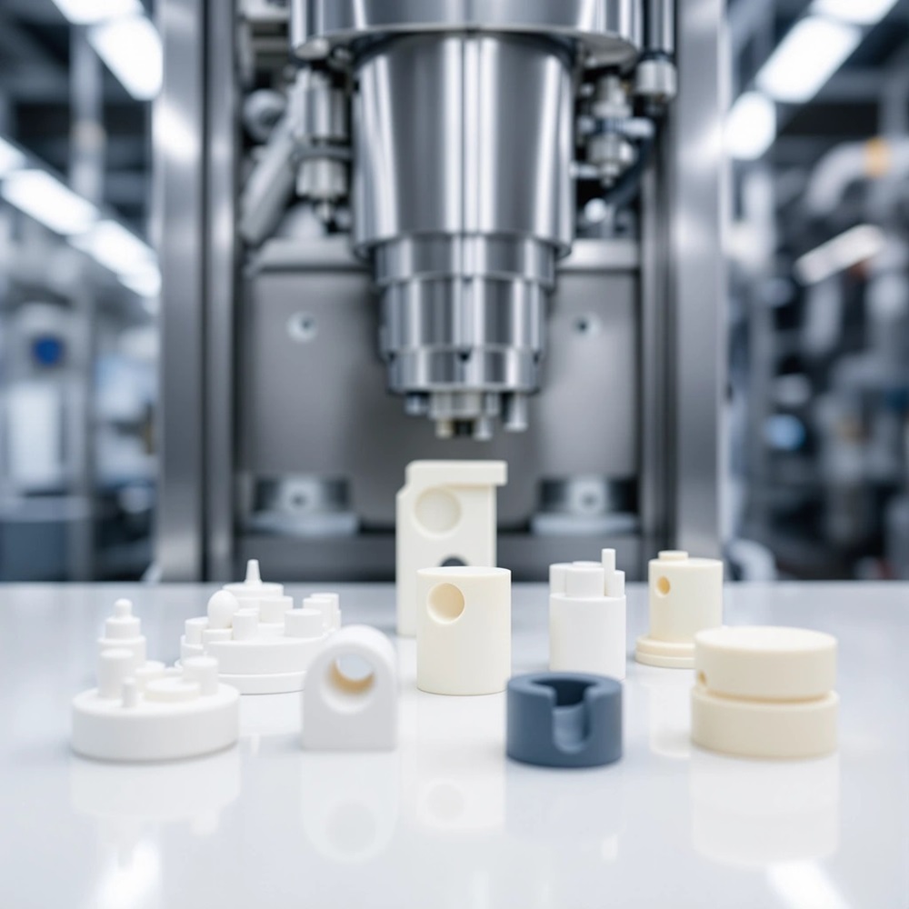
Ceramic Injection Molding (CIM) solves this challenge by combining the design freedom and high-volume efficiency of plastic injection molding with the exceptional mechanical, thermal, and wear-resistant properties of advanced ceramics. By blending submicron ceramic powders with organic binder systems, CIM enables the mass production of complex, net-shape ceramic parts with tight tolerances (±0.2% to ±0.5%) and minimal post-machining requirement.
This comprehensive guide explores the complete Ceramic Injection Molding ecosystem—from four-stage process mechanics and material selection (Zirconia, Alumina, Silicon Nitride) to DFM design rules, tooling cost structures, defect control, and supplier evaluation criteria for B2B procurement leaders and design engineers.
Understanding the Ceramic Injection Molding (CIM) Process
Four-Stage Production Workflow: Feedstock, Molding, Debinding & Sintering
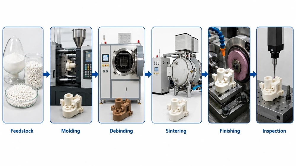
Ceramic injection molding uses four interconnected manufacturing stages that transform ceramic powder into dense, net-shape components. Feedstock preparation comes first. Fine ceramic powders mix with thermoplastic or wax-based binder systems to create injectable material. Powder loading determines final part density and shrinkage behavior. Alumina feedstocks typically contain 45–86 vol% ceramic content, Zirconia formulations range from 55–60 vol%, while Silicon Nitride suspensions operate at 45 vol% solids loading for optimal flow characteristics.
The heated feedstock fills precision mold cavities under controlled pressure and temperature after feedstock preparation. This forms green parts that retain the desired geometry. Mold temperatures and injection pressures vary based on binder viscosity and part complexity.
Next, debinding removes the organic binder system from molded components. Thermal debinding heats parts in controlled atmospheres. Solvent debinding uses chemical extraction for specific binder types, while catalytic debinding offers another rapid route based on the binder formulation. The process leaves residual binder amounts to maintain brown part integrity during handling.
Sintering completes the transformation. Ceramic particles fuse at elevated temperatures and create dense, high-strength components with predictable dimensional shrinkage. Silicon nitride parts sinter at 1750°C and achieve densities up to 97% of theoretical density. Porcelain-based formulations reach optimal densification at 1410°C and produce components with 3.04 g/cm³ density and 800±70 HV hardness. Parts exhibit their final mechanical properties and dimensional characteristics once sintering concludes.
Material Selection: Zirconia (ZrO2), Alumina (Al2O3), and Silicon Nitride (Si3N4) Properties
Material selection for ceramic injection molding applications depends on mechanical performance requirements, operating temperatures, and cost constraints. Three primary ceramic materials dominate production specifications:
| Property | Alumina (Al2O3) | Zirconia (ZrO2) | Silicon Nitride (Si3N4) |
|---|---|---|---|
| Density (g/cm³) | 3.9 | 6.0 | 3.2 |
| Vickers Hardness (GPa) | 15–18 | 12–13 | 17.2 |
| Flexural Strength (MPa) | 300–400 | 900–1200 | 700–900 |
| Fracture Toughness (MPa·m½) | 3.5–4.5 | 6.0–10.0 | 5.0–7.0 |
| Max Continuous Temp (°C) | 1500°C | ~800°C | 1200°C–1400°C |
Alumina offers the lowest material costs with moderate mechanical properties suitable for electrical insulation, wear-resistant components, and chemical processing applications. Zirconia provides exceptional fracture toughness—nearly twice that of alumina—making it ideal for impact-loaded assemblies, medical implants, and structural precision parts (though continuous operation above 800°C is restricted). Silicon Nitride delivers superior high-temperature strength and thermal shock resistance, supporting demanding aerospace, automotive, and semiconductor applications.
Minimum Order Quantities (MOQ) and Production Scalability for OEMs
Production economics in ceramic injection molding supplier relationships depend on order volume thresholds. MOQ requirements vary based on manufacturer capabilities:
- Rapid-Tooling / Prototype Services: Accept orders starting at 50–500 units for prototype validation and bridge production.
- Regional Domestic Molders: Typically require 500–5,000 units per production batch.
- High-Volume Industrial Facilities: Demand minimum orders of 5,000–50,000+ units to justify multi-cavity tooling amortization and setup costs.
Setup charges, material purchasing minimums, and inspection protocols drive these volume floors. Spreading fixed costs across larger production quantities reduces per-unit pricing by 40–70% when ordering 5–10× above MOQ floors.
Process Capabilities: Technical Specifications & Design Tolerances

Achievable Dimensional Tolerances (±0.2% to ±0.5% without Secondary Machining)
Dimensional precision in the ceramic injection molding process depends on mold design accuracy, shrinkage control, and thermal processing parameters. Standard as-sintered tolerances range from ±0.2% to ±0.5% of nominal dimensions without secondary machining operations. Advanced manufacturers achieve ±0.3% repeatability through closed-loop cavity pressure monitoring and optimized sintering profiles.
For example, a 10mm feature holds ±0.02mm to ±0.05mm variation under standard conditions. High-precision applications requiring ±0.0005″ (0.0127mm) tolerances rely on post-sintering diamond grinding or finish machining.
Wall Thickness Limitations and Design Rules (0.3mm to 6mm Range)
Wall thickness directly influences feedstock flow, debinding efficiency, and sintering uniformity. The practical design envelope spans 0.3mm to 6mm, with optimal manufacturability concentrated in the 1mm to 4mm range.
- Thin Walls (<0.4mm): Require careful evaluation of flow length, gate proximity, and green-part handling strength.
- Thick Walls (>6mm): Introduce debinding path challenges and non-uniform shrinkage risks that compromise dimensional stability.
- Uniformity Rule: Adjacent wall transitions should maintain 60–80% thickness ratios to prevent differential cooling rates and associated warpage.
Surface Finish Quality (Ra 0.4μm to 1.6μm) & As-Sintered Esthetics
As-sintered surface roughness for ceramic injection molding materials ranges from Ra 0.4μm to 1.6μm. Advanced cavity polishing to SPI A-1 standards transfers mirror-like finishes to molded surfaces, achieving Ra values below 0.4μm without post-processing. Submicron ceramic powders enable smoother surfaces but increase feedstock viscosity, balancing surface quality with moldability requirements.
Complex Geometry Capabilities: CIM vs. Traditional Ceramic CNC Machining
Ceramic injection molding enables complex geometries that are economically unattainable through conventional ceramic CNC machining. CIM forms re-entrant angles, multi-shaped blind holes, internal threads, perpendicular cross-holes, undercuts, and intricate cavities in a single net-shape operation.
While CNC machining of fired ceramics requires expensive diamond tooling, suffers short tool life, and generates 50–80% material waste, CIM completes complex shaping in the green state before final hardening—eliminating secondary machining and significantly reducing component cost.
Cost Structure Analysis: Tooling, Materials & Per-Unit Economics
Mold Development Costs: $5,000 to $50,000 Investment Breakdown
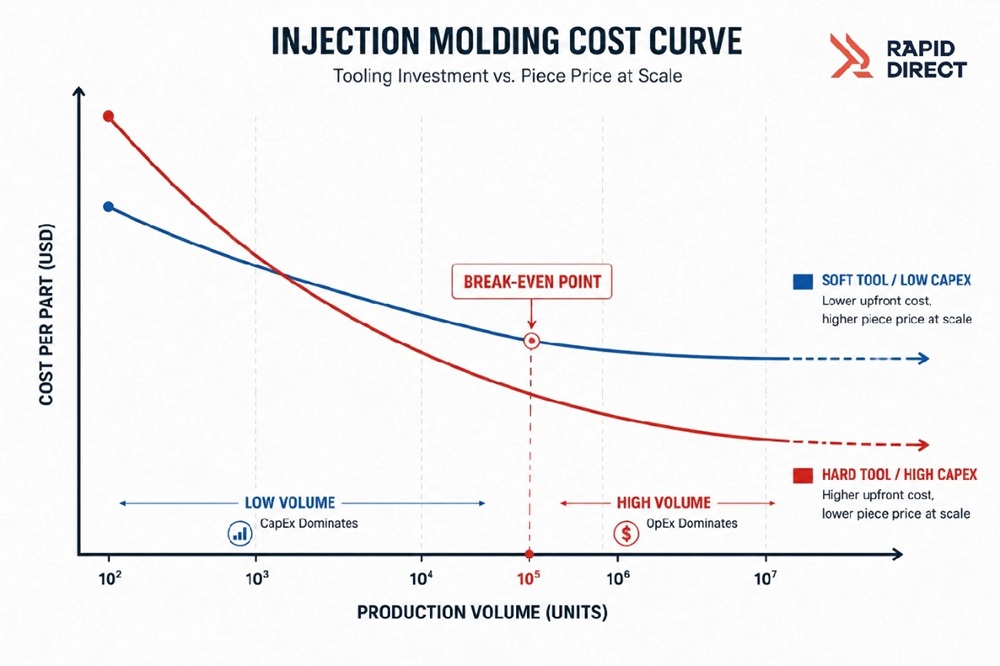
Tooling represents the primary capital investment in ceramic injection molding. Mold development expenses typically range from $5,000 to $50,000, depending on cavity count, part complexity, and required tolerances. Simple single-cavity prototype tools start near $5,000, whereas multi-cavity production molds incorporating slides, lifters, and precision shutoffs approach $50,000+.
Raw Material Costs: Pre-mixed Feedstock Pricing vs. Pure Ceramic Powder
Pre-compounded ceramic injection molding materials from specialized suppliers—including powder, binder formulation, and quality validation—are priced from $15 to $80 per kilogram. Alumina-based feedstocks occupy the lower price tier, while Zirconia and Silicon Nitride formulations command premium pricing due to advanced powder processing and binder compatibility requirements.
Break-Even Analysis: Production Volume Thresholds for Cost Justification
Ceramic injection molding process economics justify tooling investments above specific volume thresholds. Break-even points relative to CNC machining fall between 2,500 and 5,000 units for mid-complexity components. Once annual production exceeds 10,000 units, CIM achieves 30–70% unit cost reductions compared to subtractive manufacturing.
Ceramic Injection Molding (CIM) vs. Metal Injection Molding (MIM): Comparative Economics
While CIM and Metal Injection Molding (MIM) share similar tooling setups and debinding/sintering equipment, material behavior differs. MIM stainless steel feedstocks fall in a similar price bracket ($15–$80/kg), but ceramic powders induce higher abrasive wear on molds, requiring hardened tool steels or protective coatings to extend mold lifecycle economics.
Quality Control Requirements & Process Defect Prevention
Critical Debinding and Sintering Variables Affecting Thermal Shrinkage
Thermal debinding cycles require precise temperature ramp control to prevent binder degradation before extraction. Heating rates exceeding 3°C/min introduce severe cracking risks, whereas optimal vacuum debinding at 0.5–1.0°C/min ensures uniform binder removal without structural damage.
Defect Prevention: Eliminating Cracking, Warping, Binder Blisters & Density Gradients
- Cracking: Prevented by matching debinding extraction rates to part cross-sectional thickness.
- Warping: Mitigated by ensuring 60–80% wall thickness ratios and balanced gate placement.
- Binder Blisters: Controlled by multi-stage thermal profiles that allow volatile binder gases to diffuse safely.
- Density Gradients: Eliminated through uniform mold temperature distribution and optimized injection pressure profiles.
Moldflow & CAE Simulation for DFM Process Optimization
Computer-Aided Engineering (CAE) tools simulate cavity filling patterns, predicting weld lines, air traps, and sink marks before steel is cut. Integrating moldflow simulation during Design for Manufacturability (DFM) reviews reduces physical tooling iterations by 25–40% and shortens time-to-market.
Quality Assurance: CMM, Density Testing, and Measurement Protocols
Quality validation relies on Coordinate Measuring Machines (CMM) achieving ±0.003mm accuracy, optical profiling for surface finish, and Archimedes density testing (±0.01 g/cm³) to guarantee internal structural integrity before shipment.
Evaluating and Selecting a Reliable CIM Manufacturer
Production Capacity, Tooling Lead Times, and Rapid Prototyping
Evaluate potential partners based on turnaround timelines: prototype tooling typically takes 2–4 weeks, while production molds require 6–12 weeks. Partners with integrated rapid prototyping services can deliver functional ceramic samples within days for design validation.
Technical Certification Standards (ISO 9001, AS9100)
Ensure your supplier holds ISO 9001:2015 certification for general industrial quality management, or AS9100 Rev D if your components are destined for aerospace, defense, or high-reliability medical environments.
Engineering Support, DFM Collaboration & Material Traceability
Select a manufacturer that offers early co-design and DFM feedback. Complete material traceability via a Certificate of Analysis (CoA) and RoHS/REACH compliance documentation should accompany every production batch.
Conclusion & Getting a Custom CIM Quotation
Ceramic Injection Molding (CIM) offers a powerful manufacturing solution for complex, high-precision ceramic components that traditional CNC machining cannot economically produce. Delivering as-sintered tolerances of ±0.2% to ±0.5% and per-unit cost savings of up to 70% at scale, CIM is the ideal choice for demanding industrial applications requiring wear resistance, high-temperature stability, and intricate geometries.
Ready to evaluate your component design for Ceramic Injection Molding?
Whether you need high-density Zirconia components, wear-resistant Alumina parts, or custom MIM/CIM hybrid engineering support, our technical team provides full DFM analysis and competitive tooling quotes.
👉 Submit Your 3D CAD Drawing (STEP/IGES) for a Free DFM & Cost Analysis Today →
Frequently Asked Questions (FAQ)
Q1. What dimensional accuracy can be achieved with ceramic injection molding without additional machining?
Ceramic injection molding typically achieves as-sintered dimensional tolerances between ±0.2% and ±0.5% of nominal dimensions. Advanced process controls and optimized shrinkage profiles can achieve repeatability down to ±0.3% (e.g., holding ±0.03mm on a 10mm feature).
Q2. What are the typical tooling costs for ceramic injection molding projects?
Mold development costs range from $5,000 to $50,000 depending on cavity count, part complexity, and slide/lifter mechanisms. Prototype tooling starts near $5,000, while high-volume multi-cavity production molds occupy the higher tier.
Q3. At what production volume does ceramic injection molding become cost-effective?
CIM becomes cost-effective compared to CNC machining at volumes between 2,500 and 5,000 units. When annual volumes exceed 10,000 units, per-part manufacturing costs drop by 30–70%.
Q4. What wall thickness range is recommended for ceramic injection molded parts?
The recommended wall thickness envelope is 0.3mm to 6mm, with 1mm to 4mm being the ideal sweet spot for optimal flow and debinding efficiency. Maintaining a 60–80% wall thickness ratio between adjacent sections prevents warpage.
Q5. What certifications should I look for when selecting a ceramic injection molding manufacturer?
Look for ISO 9001:2015 for standard industrial components and AS9100 Rev D for aerospace/medical applications. Additionally, verify that the supplier provides batch-specific Certificates of Analysis (CoA) and RoHS compliance.