
Spur gears are among the most common types of gears in mechanical systems. They deliver high efficiency between 95–99% with minimal power loss. Powder metallurgy spur gear manufacturing offers a great way to produce these components with tight tolerances and consistent quality. Production waste remains low, especially for large-scale production. This piece explores the sintered spur gear manufacturing process and powder metallurgy gear material selection, including spur gear steel options. Custom sintered gears design specifications, sintered gear tolerance standards, and the complete RFQ process are covered for engineers seeking affordable, high-performance gear solutions.
What Are Sintered Spur Gears?
Definition and Simple Structure
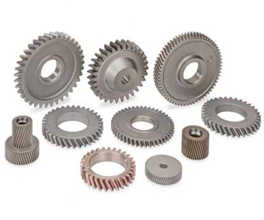
Sintered spur gears are precision components produced through the powder metallurgy process. They form directly from metal powders rather than being machined from solid metal blanks. These cylindrical gears feature teeth parallel to the gear axis, which makes them suitable for transmitting power between parallel shafts. The tooth profile follows a true involute form with full filet radius. Powder metallurgy achieves these characteristics during the compaction stage.
The structure is different from conventional gears in one critical aspect: porosity. Metal particles bond together through controlled heating below the melting point during sintering. This bonding process creates a solid component with interconnected pores throughout the material. The porous nature serves two functions. It dampens sound during operation and contributes to quieter gear performance. It also allows for oil impregnation and enables self-lubrication.
Powder Metallurgy Process Overview
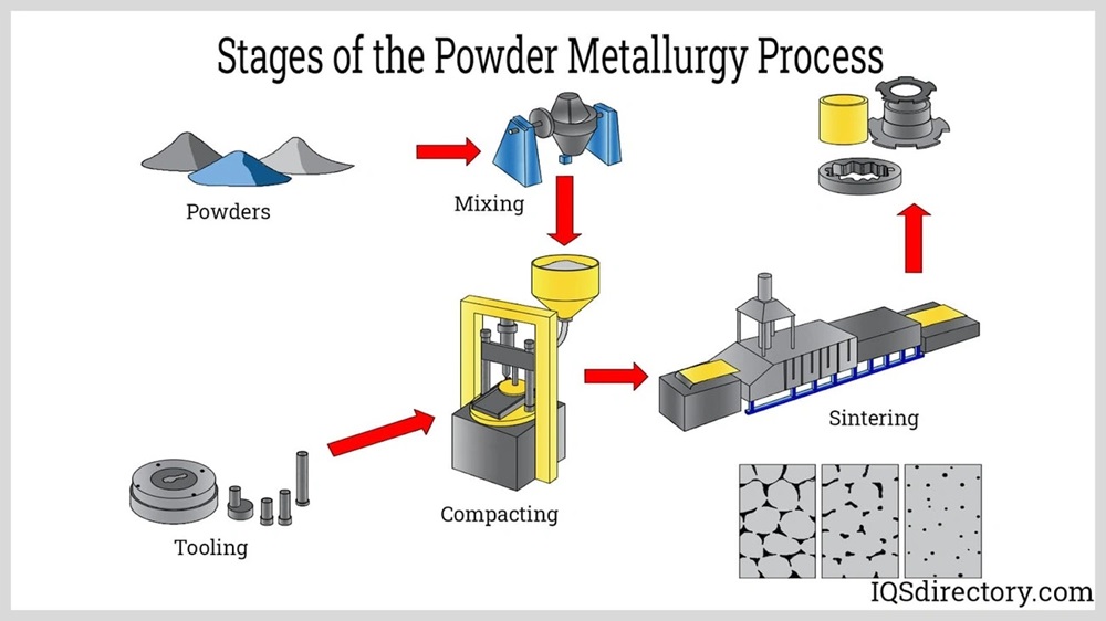
The powder metallurgy production route consists of three fundamental steps. Metal powders are mixed during the first stage to ensure a homogeneous composition of base metals and alloying elements. This blending stage determines the gear’s final material properties.
The mixed powder feeds into a die cavity after powder preparation. Hydraulic or mechanical pistons compress it under high pressure. This compaction process forms what manufacturers call a “green compact.” It’s a fragile part that holds its gear shape but lacks strength. The vertical compaction direction produces dense teeth in spur gears because the teeth align parallel to the pressing axis.
The green compact moves to a sintering furnace during the third stage. Controlled heating bonds the metal particles together. Temperatures reach 1,800°F to 2,050°F in protective atmospheres. This allows particles to fuse without complete melting. The sintering process develops the gear’s final strength and dimensional stability.
Sintered vs Machined Spur Gears: Structural Differences
The structural composition of sintered and machined gears reveals the most important differences. Conventional PM gears achieve densities between 85-93%. Machined gears reach 100% density. This density gap affects mechanical properties. Sintered gear teeth exhibit lower impact resistance by about 50% and lower contact fatigue strength by 33% compared to wrought steel gears.
Material utilization favors powder metallurgy. Sintered gears maintain material utilization rates of 95-98%. Machining achieves only 20-50% utilization. The powder metallurgy process generates scrap waste of merely 3-5%. Machining waste reaches 40-60%.
Design flexibility represents another structural advantage. Powder metallurgy builds components from the ground up rather than subtracting material from solid blocks. This additive approach enables complex geometries and lightening holes. It also allows integrated features such as cams or ratchets in a single piece. The near-net-shape forming capability minimizes secondary operations. Many sintered gears require little or no additional machining.
The porous structure provides inherent self-lubrication capabilities. Lubricants drawn into the pores via vacuum impregnation release under operational heat. This reduces friction and extends service life. This characteristic proves especially useful when you have maintenance-sensitive applications where regular lubrication access remains limited.
Powder Metallurgy Spur Gear Manufacturing Process
Metal Powder Preparation and Blending
The production of powder metallurgy spur gears starts with selecting base metal powders and alloying elements. Iron serves as the life-blood material and is often combined with copper, nickel, chromium, molybdenum, or manganese to improve specific properties. Alloying elements improve corrosion resistance and mechanical strength. Manufacturers typically add them to molten metal during powder production before atomization into prealloyed powders.
Engineers calculate weight percentages for each material based on final product requirements. Blending equipment such as V mixers combine these powders with lubricants and binders. Zinc stearate provides effective lubrication for iron-based structural parts. Acrawax offers complete removal during pre-sintering without residue. Binders like polyvinyl alcohol (PVA) deliver essential adhesion between particles and help mixed powders remain intact during compaction. A typical batch of 1,000 kg of metal powder requires about one hour of mixing. Operators must control time and speed carefully to prevent demixing caused by density or particle size differences.
Die Compaction: Forming the Green Compact
The blended powder fills a die cavity where upper and lower punches apply pressure. Softer metals require 200-400 MPa while harder materials like steel need 400-800 MPa. This compression creates a green compact with geometry and shape achieved through controlled pressure. The term “green” refers to the pressed but unsintered state. The part maintains its shape but possesses strength comparable to aspirin tablets.
Uniform pressure distribution throughout the die proves critical. Variations cause uneven density and potentially lead to weak spots and internal cracks that only become visible after sintering. Lubricants mixed during blending reduce friction between particles and the die wall. They improve green strength, tool life, and dimensional control. The green part gets carefully ejected after compaction using manual methods, powder boxes, or automated robotic arms depending on part geometry and production volume.
Sintering: High-Temperature Bonding
Green compacts enter sintering furnaces where controlled heating transforms them into solid components. Iron-based powder metallurgy spur gears undergo sintering at temperatures between 2020-2100°F. The process relies on diffusion bonding, where adjacent metal grains share molecules below the material’s melting point. This forms “necks” between grains that lock them into a rigid structure.
Metallurgists maintain controlled atmospheres during sintering to remove surface oxides and exclude oxygen. This prevents further oxidation. High-temperature sintering at 100-250 degrees above standard temperatures increases diffusion bonding. Remaining pores become more round and mechanical properties improve. This type of sintering can increase tensile strength by 30%, bending fatigue strength by 15%, and impact energy by 50%.
Secondary Operations and Finishing (Oil Impregnation & Heat Treatment)
Spur gears may undergo secondary processes after sintering to improve performance. Oil impregnation fills interconnected pores with lubricant and creates self-lubricating properties that extend service life. Heat treatment options include inductive hardening, carburizing, and nitriding. Case hardening or carburizing increases surface hardness to 45-70 HRC and develops beneficial compressive stresses. Surface densification creates pore-free cases with depths exceeding 0.7 mm while the core remains porous. Sizing operations performed after sintering hold dimensional tolerances beyond green compacting capabilities.
Material Utilization Rate: 95% vs 70% Traditional Machining
Powder metallurgy achieves material utilization exceeding 95%, with scrap rates of merely 3%. Traditional machining wastes 30-70% of material as chips and scrap. It typically achieves only 60-70% utilization for gear production. This is a big deal as it means that expensive metals see major cost savings across large production runs.
Material Selection for Sintered Spur Gears
Iron-Based Powder Metallurgy Materials
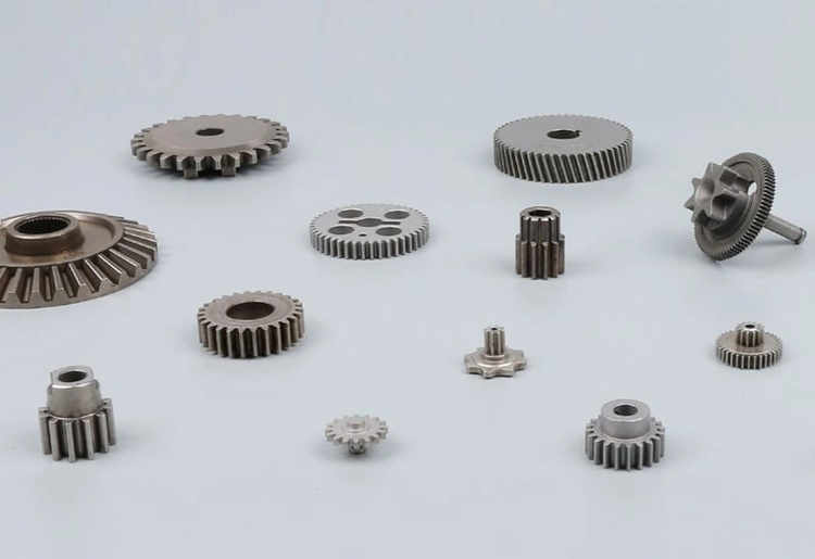
Iron-based alloys are the foundations of powder metallurgy spur gear production. Pure iron powders provide baseline strength and wear resistance. Carbon additions increase hardness and strength for moderate load applications, while nickel steel combinations provide excellent strength-to-weight ratios. Chromium additions improve wear resistance and hardenability. Molybdenum increases toughness and fatigue resistance. Material density affects power transmission efficiency. Higher density materials offer better strength and load-bearing capacity.
FC-0205 (Fe-Cu) for General Applications
FC-0205 represents a cost-effective iron-copper powder metallurgy material. It delivers moderate strength between 420-520 MPa as-sintered and increases to 650-800 MPa after heat treatment. Copper content ranging from 1.5-3.9% boosts sintering densification and dimensional stability while improving machinability to 80-85% relative to B1112 free-machining steel. This material achieves surface hardness of HRC 55-58 and core hardness of HRB 88-95 after carburizing and quenching. Sintering occurs at temperatures between 1,120-1,150°C for 20-30 minutes in endothermic gas or dissociated ammonia atmospheres. FC-0205 suits cost-sensitive applications that require secondary machining operations such as drilling, tapping, or milling.
FN-0205 (Fe-Ni) for Enhanced Strength
FN-0205 incorporates 1-3% nickel to substantially improve toughness and impact resistance. This nickel-steel sintered material achieves tensile strength between 280-480 MPa with hardness ranging from HRB 44-78, depending on density levels between 6.6-7.4 g/cm³. Nickel addition provides boosted ductility for dynamic load bearing and structural applications that require high impact resistance. The material costs about 35% more than FC-0205 but delivers superior performance in heat-treatable structural parts.
FD-0205 (Fe-Cu-Ni) for High-Load Applications
FD-0205 combines copper (1.3-1.7%) and nickel to achieve tensile strength between 610-1030 MPa. This diffusion-alloyed material delivers 30% higher fatigue limits compared to FC-0208 when case hardened to 0.5mm depth. Operating densities range from 7.0-7.2 g/cm³ with hardness spanning HRB 80 to HRC 38. FD-0205 suits high-load applications exceeding 2000 N with extended service life requirements.
Stainless Steel Powders: 316L and 17-4PH
316L stainless steel powder offers exceptional corrosion resistance with tensile strength of 390 MPa and elongation exceeding 40%. This austenitic grade has about 17% chromium, 12% nickel, and 2.5% molybdenum. It provides resistance to chloride pitting and intergranular corrosion. 17-4PH precipitation-hardening stainless steel achieves tensile strength exceeding 1310 MPa after aging treatment. The 17-4PH composition has 17% chromium, 4% nickel, and 3% copper. It delivers hardness above HRC 40 through precipitation strengthening.
Carburizing Grades: 4605 and 8620 Steel
PM 4605 nickel-molybdenum low-alloy steel responds well to heat treatment and achieves 45-55 HRC after quenching and tempering. AISI 8620 steel produced via powder metallurgy demonstrates substantial strength improvement after carburization. Ultimate tensile strength increases by 134.4% to 138.1%. Carburized layers average 29.68-42.99 µm thickness and substantially increase hardness while reducing wear depth by 56.7% under 30 N loads.
Custom Sintered Gear Design Specifications
Module Range: 0.5–2.5mm for Powder Metallurgy
Powder metallurgy spur gear manufacturing accommodates module values between 0.5mm and 2.5mm for standard production capabilities. The minimum modulus must be 0.5, although 0.25 is achievable in some cases. Module selection affects tooth size and torque capacity. Larger values provide thicker and stronger teeth suited for heavy-load transmission.
Dimension & Tonnage Capabilities: Up to 150mm Diameter with 1000-Ton Presses
Geometric constraints in powder metallurgy impose size boundaries on custom sintered gears. Diameter limitations cap at 150mm in most cases, while overall height stays within 60mm. Heavy-duty 1,000-ton compaction presses make these dimensions achievable. Standard PM gears range from 5mm to 150mm in diameter and 5mm to 60mm in height. The aspect ratio must stay within 8:1 to maintain structural integrity during compaction and ejection. Wall thickness needs at least 1.52mm to ensure tooling durability.
Sintered Gear Tolerance Standards: AGMA 8-10 / ISO Standards
Sintered spur gears achieve DIN 3961 grade 8 accuracy levels. Surface densification through rolling operations can boost AGMA quality ratings from Q6 to Q9. The gear quality after heat treatment reaches DIN class 8 with surface roughness of Ra=1.2 µm. Diameter precision reaches IT7-9 according to ISO 286 fundamental tolerances, while length precision ranges between IT10-12.
Pressure Angle Selection: 20° Standard vs Custom Variations
The 20° pressure angle serves as the industry standard for powder metallurgy spur gear manufacturing. This angle provides wider tooth bases and allows additional load capacity coupled with better lubrication in the gear mesh. Pressure angles of 22.5°, 25°, or 30° have been used for specialty applications where strength outweighs noise concerns.
Face Width, Draft Angles, and Load Capacity Considerations
Most compaction presses restrict face width to well under 3 inches. Boss features require a minimum 12° draft on each side to ensure smooth ejection from the die. PM gears achieve 85-95% of machined gear load capacity at equivalent geometry when designed well.
RFQ Process for Custom Sintered Spur Gears
Required Technical Information & Drawing Formats (STEP, IGES, DWG)
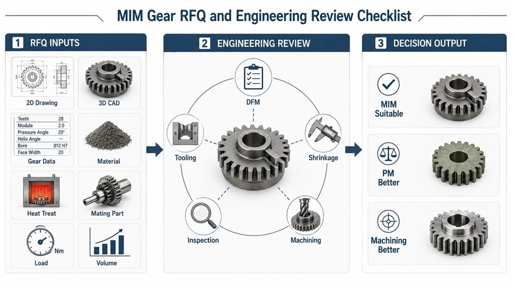
An RFQ for custom sintered gears requires controlled 2D drawings showing critical dimensions, tooth data, bore details and revision control. CAD files in STEP, IGES, DWG or DXF formats support geometry review. Specifications must include gear type, module or diametral pitch, pressure angle, tooth count, face width, outer diameter, inner diameter, bore dimensions and keyway or spline details.
Material Selection Based on Load Requirements
Material expectations should address operating conditions including load, speed, wear, corrosion, noise and cost requirements. Torque, speed and duty cycle shared early allow proper matching of material and tooth modification to the application.
Volume Thresholds: When to Choose Powder Metallurgy
Powder metallurgy becomes cost-competitive at 5,000-10,000 parts for suitable geometries. Break-even occurs at 15,000-30,000 gears depending on complexity. PM delivers 45-60% cost savings versus hobbing at 100K+ annual volume.
Tooling Costs and Amortization at 100k+ Parts/Year
Tooling costs range from USD 4,000-USD 20,000 for simple geometries to USD 120,000 for complex dies. So high-volume programs reach a five-year net benefit of USD 19,925,000 after tooling amortization.
Lead Time Expectations and Free DFM Analysis
Simple designs require 2-3 weeks. Medium complexity orders take 4-6 weeks, and customized gears need 8-12 weeks or longer. Feasibility reviews complete within 3-5 working days. Free DFM analysis optimizes layouts and cuts costs by 20-30%.
Conclusion
Powder metallurgy delivers a compelling solution to produce sintered spur gears. It combines material efficiency above 95% with consistent quality and near-net-shape forming capabilities. Engineers who select this manufacturing route get access to diverse material options from cost-effective FC-0205 to high-strength FD-0205 and corrosion-resistant stainless steel grades. Each grade is tailored to specific load requirements and operating conditions.
The technology proves especially advantageous for high-volume applications. Programs that exceed 100,000 parts annually achieve 45-60% cost savings compared to traditional machining. Successful implementation requires careful attention to design specifications and material selection lined up with load demands. A full RFQ documentation package will optimize tooling investments and ensure long-term manufacturing success.