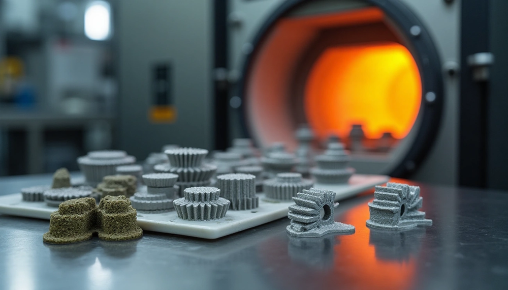
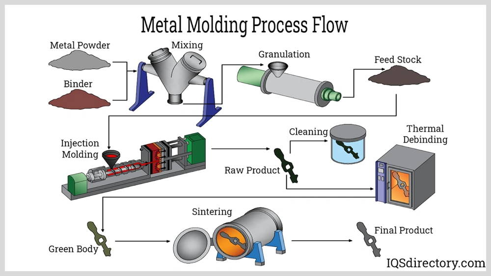
MIM process makes metal components with complex shapes that traditional manufacturing techniques struggle to produce. Metal injection molding creates parts with density and uniformity that match or surpass conventional sintering properties. The technique comes with major challenges during the sintering phase, especially when dealing with intricate geometries.
The process combines metallic powders with a binder material. The mix contains 40-68% metal powder and 32-60% binder by volume. Metal particles weld together during sintering to develop the final mechanical properties. Parts shrink by 15-20% as metal particles fuse in the manufacturing process. This shrinkage can create defects in complex-shaped components. MIM metal production often faces problems like cracking, slumping, warpage, and blisters during debinding and sintering. The manufacturing works best for small and medium-sized parts but runs into technical limits with larger components, especially in primary binder removal.
This piece gets into the specific challenges that complex MIM components face during sintering. It explores ways to overcome these obstacles while keeping the exceptional quality that makes the metal injection molding process valuable in medical devices, electronics, firearms, and automotive manufacturing.
Thermal and Geometric Constraints in Complex-Shape Sintering
Complex geometries in metal injection molding create many challenges during sintering because of physical constraints. Parts need precise control over shrinkage, thermal gradients, and support structures to meet quality standards.
Shrinkage Variability in Asymmetric Geometries
Shrinkage stands out as a major challenge in MIM manufacturing. Green parts typically shrink by 20% during sintering. Material composition can change this ratio between 15-20%. Asymmetric components face bigger problems because shrinkage doesn’t happen evenly across different features.
Complex-shaped MIM metal components develop stress points that can cause warping. Dimensional accuracy becomes harder to achieve since shrinkage is anisotropic—it’s higher in the printing direction compared to the construction plane. Engineers need to factor in these variations when designing molds and add compensation based on the materials used and geometric complexity.
Thermal Gradient Effects on Wall Thickness
Temperature distribution plays a crucial role in determining the final part’s quality. Uneven cooling rates during sintering create varying densification levels when thermal gradients exist.
Higher temperature gradients (0.230 to 0.657°C/mm) along the radial direction help create uniform grain sizes. But rapid heating creates temperature differences between the surface and the interior. This generates thermal stress and can form cracks. Parts have a higher chance of developing defects as heating rates increase.
Wall thickness variations make parts more vulnerable to thermal gradient effects. Thick sections hold heat longer than thin areas. This difference causes uneven shrinkage and might distort the part after cooling.
Support Structure Limitations in Thin-Walled Parts
Thin-walled features under 0.5mm thickness create serious problems during MIM metal injection molding. These delicate structures can break easily, even before sintering begins.
Complex-shaped parts need proper support during debinding and sintering to avoid distortion. Long spans, cantilevers, and delicate points often need special fixtures. Designers should stick to standard or flat debinding and sintering supports instead of custom ones that drive up tooling costs.
Manufacturers sometimes add extra features to parts to avoid using additional support structures. These support systems play a key role in preventing warpage and keeping thin-walled sections dimensionally stable.
Atmosphere Control and Material Compatibility Issues
Atmosphere management creates major challenges in the mim manufacturing process. Wrong atmospheric conditions can damage part integrity and functional properties. The control of sintering environments plays a crucial role when manufacturing complex-shaped components.
Oxidation Risk in Open-Pore Structures
Metal parts with open-pore structures in mim are vulnerable to oxidation that can damage their mechanical properties. Unwanted chemical reactions like oxidation make it necessary to control the atmosphere precisely. The heating rates need to stay low when the sintering process begins. Components that have interconnected open pores from 15.2% to 30.7% face higher oxidation risks as pore volume increases. These open-pore structures work best for applications like bone ingrowth where the optimum pore size ranges from 100-500 μm. They need careful atmosphere management to stay structurally sound.
Binder Residue Impact on Alloy Composition
The final metal composition changes substantially due to leftover binder components in metal injection molding. Permanent magnets lose their magnetic characteristics when carbon from binder systems contaminates them. The material properties also suffer when oxygen enters during various metal injection molding steps. Some powders show oxygen levels of 0.35 wt.%. A good binder system should achieve a low residual carbon content after thermal debinding. Poor binder management makes the general shrinkage of 12% to 18% unpredictable. This affects dimensional tolerances that usually range from ±0.05% to ±0.3%.
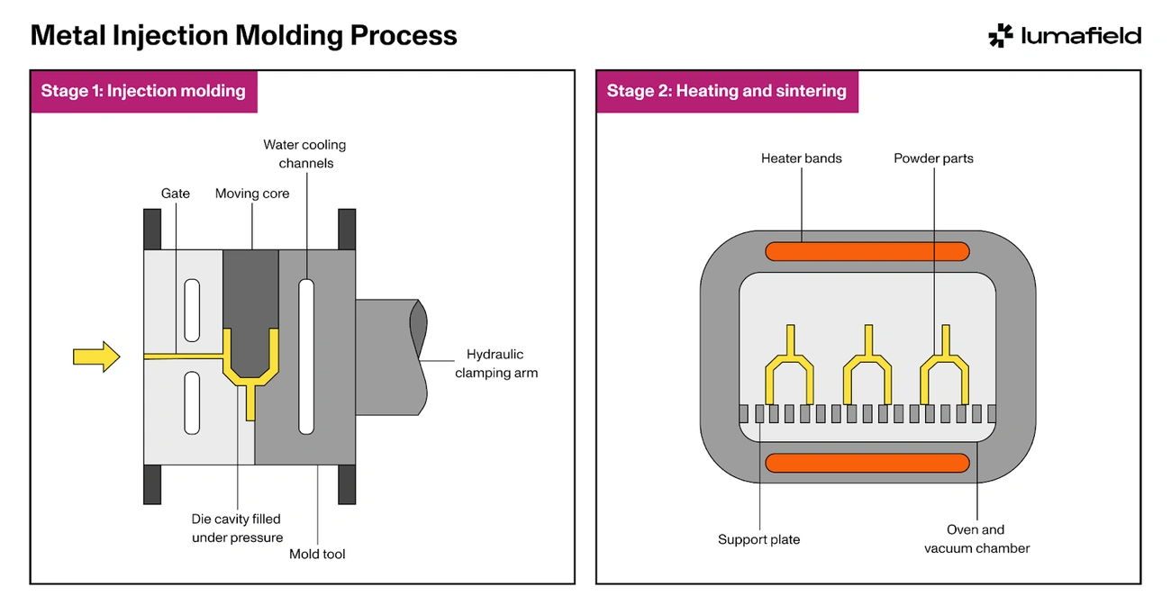
Inert Gas vs. Vacuum Sintering for Complex MIM Metal
The choice between inert gas and vacuum sintering shapes the final mim manufacturing results. Inert gas sintering uses argon that prevents oxidation and ensures high product purity. Controlled atmosphere sintering with specific gas mixtures like nitrogen or hydrogen provides better control over sintering kinetics. It also removes surface oxides effectively. Vacuum sintering gives the best results for complex mim metal components by reducing contamination risks. However, inert gas atmospheres might work better when additive metal loss becomes an issue. The SINTERFLEX® Atmosphere Control System helps optimize oxygen and carbon content control. It creates carbon-neutral atmospheres that stop decarburization and produce more uniform carbon content in sintered parts.
Common Defects in Sintering of Complex MIM Components
Defect formation creates major obstacles in the mim metal injection molding process. These defects determine if complex components meet strict quality standards. Manufacturers can implement preventive measures by understanding these common defects.
Cracking Due to Uneven Densification
Cracks in mim metal components happen when residual stress exceeds fracture strength. The shrinkage of added molten layers creates tensile stress on the part’s top face. Grain boundary crack growth emerges as the main cracking mechanism because of grain boundaries’ brittleness and impurity segregation. You’ll often find lack-of-fusion defects as low-sphericity, crack-like elongated voids that sometimes contain unfused powder. The scanning strategy guides grain morphologies and residual stress distribution, which makes it vital to prevent cracks. The good news is that appropriate supporting structures can fully suppress these cracks.
Slumping in Unsupported Overhangs
Parts become structurally weaker during sintering because of heavy diffusion flows and sometimes liquid phase presence. Gravity causes frustrating distortions in components with overhanging or unsupported sections. Parts become especially vulnerable to gravity-induced deformation between complete binder removal and the start of necking. The risk of slumping increases for parts without flat elements or stable positioning. Sintering support structures made from similar materials can prevent this issue. These structures should match the shrinkage behavior, though this adds to production costs through material scrap.
Blistering from Rapid Binder Decomposition
Blisters form when heating rates go beyond optimal ranges during thermal decomposition. Binder components break down at specific temperature thresholds. Quick temperature increases trap gaseous decomposition products inside the part structure. This trapped gas builds internal pressure and creates surface blisters. Laminar flow in the furnace helps remove decomposed binder in the gaseous phase and optimizes efficiency. Blister formation also happens due to binder swelling and residual stress differences between surface and interior sections.
Distortion from Non-uniform Shrinkage
Warping or distortion in final parts happens because of non-uniform shrinkage. This is a big deal as it means that dimensional accuracy and functionality are affected. Components maintain geometric integrity only when the standard 15-20% shrinkage during sintering occurs evenly. Different wall thickness creates uneven shrinkage rates. The cooling process plays a vital role – uneven cooling generates internal stresses that demonstrate as warpage. Complex geometries or varying cross-sections need specially controlled heating profiles to handle shrinkage variations. Using multimodal powder distributions can lower overall shrinkage from about 20% to 12%. This reduction minimizes friction between staging surfaces and components.
Process Optimization Strategies for Complex MIM Shapes
Manufacturing complex MIM components requires systematic optimization of process parameters to overcome challenges. The process requires precise control throughout the manufacturing sequence to achieve superior dimensional accuracy and material properties.
Controlled Heating Profiles for Uniform Necking
The lifeblood of successful sintering lies in optimal heating rates. Thermal debinding uses adjusted heating rates of 1°C/min to prevent defects. Temperature ramps under careful control ensure uniform necking—metal powders bridge through thermal diffusion. The thermal cycle must give sufficient time for binder decomposition before necking starts. Early sintering can trap volatiles that create internal defects.
Complex geometries need extended holding times at strategic temperature thresholds to minimize differential shrinkage. Research shows parts with multi-component binders perform best with 2-3 hour holding periods at specific temperature plateaus. These pauses let thermal equilibrium develop across varying wall thicknesses.
Multi-stage Debinding to Minimize Internal Stress
A combination of thermal and solvent debinding techniques cuts processing time dramatically. This hybrid approach removes up to 40% of binder volume through solvent action before thermal processes start. Thermal debinding then eliminates remaining components one by one to minimize internal stress buildup.
The process follows carefully coordinated stages. The first stage heats to 477K with a 2-hour hold. Next comes a gradual temperature rise to 755K at 1K/min, followed by a 3-hour holding period. This methodical approach stops sudden vapor pressure buildup that can distort complex geometries.
Simulation-Based Prediction of Shrinkage Zones
Finite element analysis plays a vital role in predicting dimensional changes of complex MIM parts. Computer simulations model the 15-20% linear shrinkage common in the mim manufacturing process. Advanced numerical modeling helps manufacturers anticipate stress/strain patterns throughout the sintering cycle.
These simulation tools use various shrinkage models to review process parameter effects on part manufacturability. The Taguchi-GRA-PCA method determines the best solutions for conflicting requirements and minimizes dimensional variations. Engineers make use of information to modify tool designs, which prevents trial-and-error approaches that get pricey.
Use of μ-MIM® 2-in-1 Furnace for Precision Control
The most important technological advancement in mim metal production comes from integrated furnace systems that combine debinding and sintering operations. The μ-MIM® 2-in-1 furnace eliminates handling of fragile brown parts between process stages. High-quality sintered components need this technology to maintain precise atmospheric control.
JH MIM brings nearly 20 years of experience in metal injection molding and powder metallurgy. Their factories span more than 18,000 square meters with world-class equipment and 150 skilled workers. Their expertise in precise atmosphere management during thermal cycling will give optimal results, making them your best metal injection molding manufacturer in China.
Conclusion
Metal injection molding is a powerful manufacturing technique to create complex metal components. Sintering challenges remain major hurdles that manufacturers must overcome. The success of MIM production needs careful control in every processing phase. Smart thermal management and controlled heating profiles with strategic holding periods help reduce defects. These steps ensure uniform densification in parts with different shapes. The choice of atmosphere also makes a big difference. Vacuum or inert gas environments each work better for specific materials.
Final components must account for a substantial 15-20% shrinkage during the process. Their dimensional accuracy largely depends on this factor. Engineers now use simulation tools to spot stress points and possible deformation areas before starting production. Despite these challenges, MIM technology shines when creating intricate shapes with high precision for the medical, automotive, and electronics industries.
Smart defect prevention strategies have changed the game. Multi-stage debinding and specialized support structures now make it possible to manufacture previously “impossible” shapes. JH MIM brings nearly 20 years of experience in metal injection molding and powder metallurgy. The company’s factories span more than 18,000 square meters. World-class equipment and 150 skilled workers deliver precision-engineered products to global customers. This makes JH MIM China’s leading metal injection molding manufacturer.
MIM components with complex shapes need careful monitoring of thermal gradients, atmosphere, and support strategies during sintering. These extra steps make manufacturing more complex. Yet they help create high-performance metal parts with intricate features that traditional manufacturing can’t match. Companies that master these specialized sintering techniques gain a competitive edge. They can explore more design possibilities and get better material performance.
FAQs
Q1. What are the main challenges in sintering complex-shaped MIM components? The primary challenges include managing shrinkage variability in asymmetric geometries, controlling thermal gradients across varying wall thicknesses, and providing adequate support for thin-walled parts during the sintering process.
Q2. How does the atmosphere control affect the quality of MIM parts? Atmosphere control is crucial for preventing oxidation in open-pore structures, managing binder residue impact on alloy composition, and ensuring optimal sintering conditions. The choice between inert gas and vacuum sintering can significantly influence the final product quality.
Q3. What are common defects in sintered MIM components, and how can they be prevented? Common defects include cracking due to uneven densification, slumping in unsupported overhangs, blistering from rapid binder decomposition, and distortion from non-uniform shrinkage. These can be prevented through controlled heating profiles, proper support structures, and optimized binder removal processes.
Q4. How does simulation technology help in the MIM sintering process? Simulation-based prediction of shrinkage zones helps anticipate stress/strain patterns throughout the sintering cycle. This allows manufacturers to modify tool designs and process parameters to minimize dimensional variations and prevent costly trial-and-error approaches.
Q5. What role does heating profile control play in successful MIM sintering? Controlled heating profiles are essential for achieving uniform necking, minimizing internal stress, and ensuring even densification across complex geometries. Multi-stage heating with strategic holding periods helps manage differential shrinkage and prevents defect formation in MIM parts.