
Sintered Synchronizer Hub Manufacturing: Powder Metallurgy Advantages and DFM Best Practices
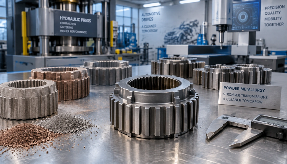
Modern automotive gearboxes rely heavily on precision components engineered via powder metallurgy (PM). Among these, the synchronizer hub is a critical transmission component that ensures smooth gear transitions in manual and dual-clutch transmissions by synchronizing shaft speeds prior to engagement. Powder metallurgy delivers distinct manufacturing advantages for synchronizer gear hubs: near-net-shape production with complex integrated splines, exceptional raw material utilization of 95–98%, and overall cost reductions of 15–40% by eliminating secondary machining. This technical guide examines synchronizer hub function, powder metallurgy advantages, sintering manufacturing steps, and Design for Manufacturability (DFM) best practices for high-load transmission applications.
Synchronizer Hub Function and Design Requirements

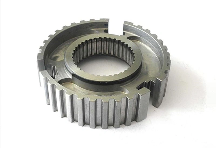
Manual Transmission Synchronizer Hub Components
The synchronizer hub functions as the structural anchor of the synchronizer assembly. It establishes a rigid mechanical connection to the transmission shaft via internal splines, preventing relative rotation while allowing required axial positioning. External splines on the hub’s outer diameter maintain constant mesh with the corresponding internal splines of the sliding synchronizer sleeve. Dedicated slots or keyways integrated into the hub house locking elements (struts, keys, or detent balls), which rotate alongside the hub and generate the preliminary synchronization load against the blocking ring. Retaining springs installed on both sides of the hub ensure consistent key location throughout high-frequency shift cycles.
Synchronizer Hub and Sleeve Interaction Mechanics
During gear selection, the shift fork moves the sliding sleeve axially across the hub’s external splines toward the target gear. The sleeve pushes the locking keys into engagement with the synchronizer ring, forcing its internal friction cone against the gear’s mating cone. This action matches the rotational speeds of the shaft and target gear. Once speed synchronization is complete, the sleeve’s engagement teeth slide past the blocking ring teeth to lock directly with the target gear’s clutch teeth, establishing a rigid power flow path. Torque is then transferred seamlessly from the transmission shaft through the synchronizer hub and sleeve to the selected gear ratio.
Material and Dimensional Tolerance Specifications
Transmission synchronizer hubs operate under high fatigue loads, rotational shear stresses, and operating temperatures exceeding 150°C. While traditional forged hubs relied on medium-carbon alloy steels (such as SAE 1045 or 4140), modern automotive applications increasingly utilize high-density PM steel formulations, such as pre-alloyed or diffusion-alloyed powders (Fe-Cu-Ni-Mo). These sintered materials provide excellent fatigue limits, dimensional stability, and surface durability across service lifetimes exceeding 300,000 kilometers in passenger vehicles and 800,000 kilometers in heavy commercial applications.
Powder Metallurgy Advantages for Synchronizer Hub Manufacturing
Near-Net-Shape Production with Integrated Splines
Powder metallurgy enables the simultaneous compaction of intricate internal and external spline geometries in a single pressing stroke. This near-net-shape capability eliminates multi-axis machining operations required by conventional forging routes. The controlled axial compaction process forms synchronizer hubs complete with drive splines, detent slots, and chamfers, ensuring precise concentricity between inner shaft-engagement features and outer sleeve-interface splines.
Material Efficiency: 95–98% Powder Utilization
Compared to traditional machining from solid forgings—where material scrap rates can range from 40% to 70%—powder metallurgy achieves a raw material utilization rate of 95–98%. In optimized high-volume production, scrap generation stays below 3–5%. Uncompacted powder can be reclaimed directly into the batching process, significantly reducing material waste when processing high-grade alloy powders.
Dimensional Accuracy for Internal and External Features
Directly after sintering, precision PM hubs achieve dimensional tolerance grades of IT 8–9. When followed by precision sizing or coining operations, dimensional tolerances can be refined to IT 5–7 ranges. Rigid carbide tooling combined with high-tonnage compaction presses maintains strict dimensional repeatability across multi-million part production runs.
Cost Reduction Through Eliminated Broaching and Gear-Hobbing Operations
Switching from conventional machining to powder metallurgy reduces total manufacturing costs by 15% to 40%. By eliminating specialized broaching for internal splines and gear hobbing for external teeth, production lead times and labor costs are dramatically reduced. Additionally, sintering consumes approximately 1.8 kWh/kg of energy, representing a substantial energy saving compared to conventional drop-forging processes (approx. 3.0 kWh/kg).
Sintered Synchronizer Hub Manufacturing Process
Die Design and Powder Compaction for Complex Internal/External Splines
Multi-action hydraulic or mechanical presses equipped with multi-level tooling systems handle the complex multi-tiered profile of synchronizer hubs. Tooling punch movements are controlled independently to apply uniform compaction pressures (600–750 MPa) across varying wall sections. This ensures uniform density distribution across both outer spline teeth and inner spline roots, preventing density gradients that could cause distortion during sintering.
Sintering Parameters and Sinter-Hardening for Automotive Strength
Compacted green bodies are sintered in continuous mesh-belt or roller-hearth furnaces at 1120°C to 1280°C in a protective endothermic or nitrogen-hydrogen atmosphere. Advanced automotive hubs utilize sinter-hardening technology, where rapid gas quenching in the furnace cooling zone (cooling rates of 1.5–5.0°C/s) converts the austenitic phase directly into a high-strength martensitic microstructure. This eliminates the need for separate oil-quenching heat treatment, minimizing thermal distortion and maintaining tight tolerances.
Secondary Operations: Precision Sizing, Machining, and Surface Treatment
Where extreme dimensional precision or specific surface finishes are required, post-sintering operations are applied:
- Precision Sizing (Coining): Re-presses the sintered component in a closed die to calibrate spline pitch diameters and axial parallelism.
- Deburring & Polishing: Centrifugal or vibratory finishing removes micro-burrs from spline tooth edges and keyways.
- Induction Hardening / Surface Treatment: Selective induction heating can be applied to specific high-wear areas if required.
Quality Control and Density/Dimensional Verification
Quality assurance includes non-destructive density checks, CMM profile scanning for spline pitch error, microstructural phase verification, and radial crush strength testing. Target component densities are strictly maintained between 6.8 g/cm³ and 7.4 g/cm³ depending on torque requirements.
DFM Best Practices for Synchronizer Gear Hub Design
Wall Thickness Requirements for Uniform Powder Density Distribution
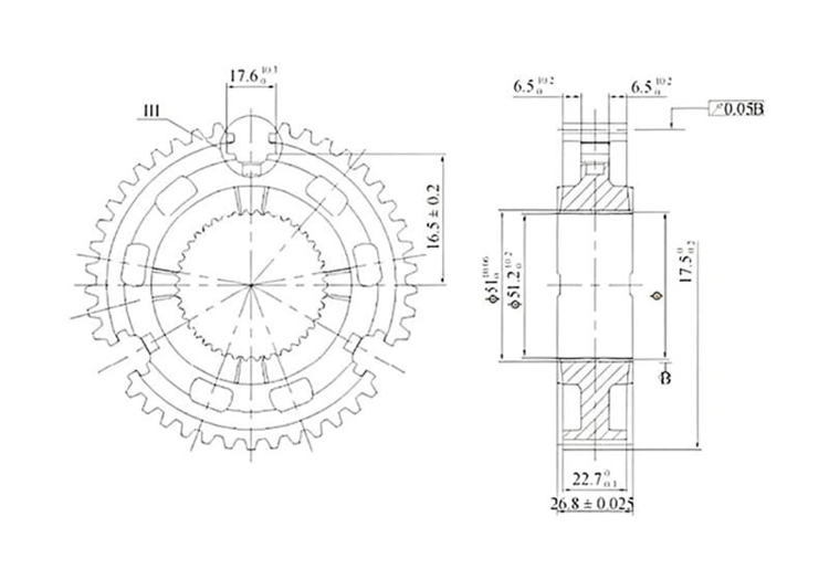
Maintain nominal wall thickness between 1.5 mm and 15 mm to facilitate uniform powder flow during die filling. The minimum recommended wall thickness is 1.52 mm. Abrupt cross-sectional changes exceeding a 3:1 thickness ratio should be avoided to prevent density variations and internal stress concentration.
Spline Geometry Constraints, Radius Transitions, and Ejection Angles
Incorporate draft angles of 0.5°–1.0° per side on external spline features and 1.0°–2.0° on internal cavities where feasible to ensure smooth die ejection. All internal corners and spline root transitions should specify generous fillet radii (R ≥ 0.5 mm) to lower punch stress during compaction and increase fatigue strength.
Surface Finish and Chamfer Specifications for Smooth Sleeve Engagement
Specify lead-in chamfers of 30°–45° with flat crests (0.13–0.38 mm) on external spline tooth tips. Smooth, radiused transitions between chamfer faces and tooth flanks prevent burr formation and ensure low-friction sliding engagement with the synchronizer sleeve.
Density Targets: 6.8–7.2+ g/cm³ for High-Load Transmission Demands
Target overall density ranges of 6.8–7.2 g/cm³ for standard manual transmission applications. For high-torque passenger car and commercial vehicle transmissions, density targets should be specified at 7.0–7.4 g/cm³ (or localized surface rolling) to maximize bending fatigue strength and impact resistance.
Material Selection: Fe-Cu-C vs. Diffusion-Alloyed Ni-Mo-C Steels
- Fe-Cu-C Systems (e.g., FC-0208): Cost-effective solution offering excellent compressibility, adequate tensile strength, and easy dimensional control for moderate-duty hubs.
- Diffusion-Alloyed Steels (e.g., Distaloy AE / AB with Ni, Cu, Mo): Delivers exceptional core toughness, high contact fatigue strength, and uniform response to sinter-hardening for heavy-duty transmission demands.
Conclusion
Powder metallurgy has transformed automotive synchronizer hub manufacturing by combining near-net-shape capability with 95–98% material efficiency. By replacing complex broaching and hobbing operations with precision die compaction and sinter-hardening, PM cuts component manufacturing costs by 15% to 40% while meeting rigid OEM strength and noise-vibration-harshness (NVH) requirements. Adhering to fundamental DFM practices—such as uniform wall thickness, generous fillet radii, and optimal target densities (6.8–7.2+ g/cm³)—ensures reliable performance in modern transmission platforms.
Frequently Asked Questions (FAQs)
Q1. What are the primary manufacturing advantages of powder metallurgy for synchronizer hubs?
Powder metallurgy enables near-net-shape production with integrated internal and external splines in a single compaction step. It achieves 95–98% material utilization and reduces manufacturing costs by 15–40% by eliminating secondary broaching and hobbing operations.
Q2. What density levels are required for sintered synchronizer hubs in automotive gearboxes?
Standard transmission applications require a sintered density between 6.8 and 7.2 g/cm³. High-torque automotive and commercial vehicle applications target densities of 7.0 to 7.4 g/cm³ to ensure optimal fatigue resistance and load capacity.
Q3. How does sinter-hardening improve the mechanical properties of synchronizer hubs?
Sinter-hardening integrates sintering and heat treatment into a single furnace cycle by rapidly cooling the parts with gas quenching in the cooling zone. This creates a high-strength martensitic microstructure without oil quenching, minimizing thermal distortion and retaining dimensional precision.
Q4. What wall thickness constraints should be applied in synchronizer hub DFM?
Designers should specify wall thicknesses between 1.5 mm and 15 mm (minimum 1.52 mm) and limit cross-sectional variations to a maximum ratio of 3:1 to ensure uniform powder filling and consistent density throughout the part.
Q5. Why are lead-in chamfers required on synchronizer hub spline teeth?
Spline tooth chamfers (typically 30°–45° with 0.13–0.38 mm flats) guide the sliding sleeve during gear shifts, preventing edge burring, reducing shift effort, and extending the operational life of the entire synchronizer assembly.
Powder metallurgy enables near-net-shape production with integrated internal and external splines in a single compaction step. It achieves 95–98% material utilization and reduces manufacturing costs by 15–40% by eliminating secondary broaching and hobbing operations.
Standard transmission applications require a sintered density between 6.8 and 7.2 g/cm³. High-torque automotive and commercial vehicle applications target densities of 7.0 to 7.4 g/cm³ to ensure optimal fatigue resistance and load capacity.
Sinter-hardening integrates sintering and heat treatment into a single furnace cycle by rapidly cooling the parts with gas quenching in the cooling zone. This creates a high-strength martensitic microstructure without oil quenching, minimizing thermal distortion and retaining dimensional precision.
Designers should specify wall thicknesses between 1.5 mm and 15 mm (minimum 1.52 mm) and limit cross-sectional variations to a maximum ratio of 3:1 to ensure uniform powder filling and consistent density throughout the part.
Spline tooth chamfers (typically 30°–45° with 0.13–0.38 mm flats) guide the sliding sleeve during gear shifts, preventing edge burring, reducing shift effort, and extending the operational life of the entire synchronizer assembly.