
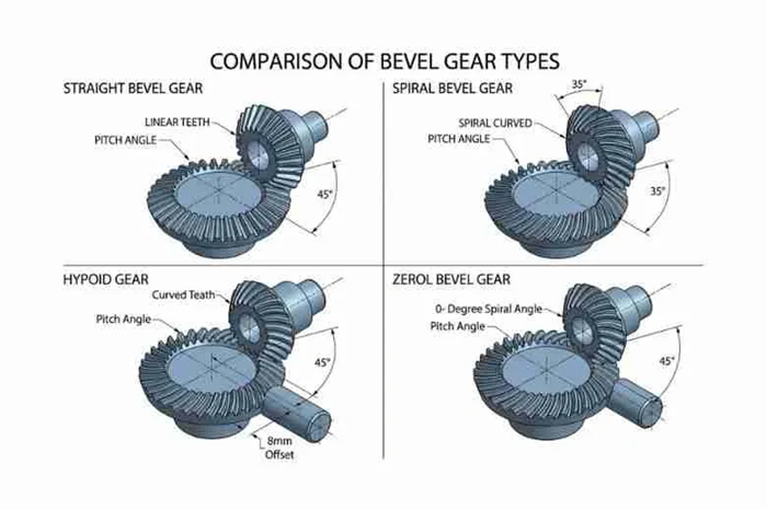
Bevel gears transfer power between shafts that intersect at an angle and offer efficiency rates between 97% and 99.5%. Their conical tooth geometry enables smooth torque transmission. Differential failures often stem from incorrect gear type specification, and aerospace engineers cite misalignment as the leading cause of premature wear. Selecting the right manufacturing method is critical for optimal performance then.
Sintered bevel gears, produced through powder metallurgy, present engineers with design opportunities and constraints compared to traditional machined options. Understanding sintered gear design parameters, material selection trade-offs, and cost-performance considerations will help engineers avoid pricey mistakes and achieve reliable power transmission in their applications, whether specifying a spiral bevel gear or straight bevel gear configuration.
Understanding Sintered Bevel Gears: Powder Metallurgy Fundamentals
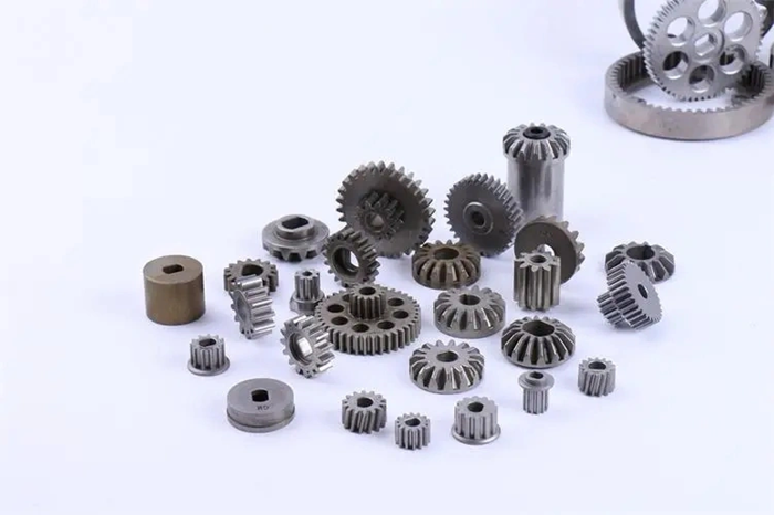
What Makes Sintered Bevel Gears Different from Machined Gears
Powder metallurgy creates bevel gear geometries through material consolidation rather than removal. The near-net-shape manufacturing process uses up to 97 percent of raw materials, whereas traditional machining wastes material through cutting and shaping operations. This fundamental difference affects both production economics and performance characteristics.
Sintered bevel gears exhibit a porous structure that provides natural noise reduction during operation. This controlled porosity allows for oil impregnation and creates self-lubricating properties that extend service life and reduce maintenance requirements. Machined gears require external lubrication systems throughout their operational life.
Complex bevel gear geometries that require multiple machining operations can be formed in a single compaction step through powder metallurgy. This proves especially valuable for differential assemblies and right-angle drive systems where intricate tooth profiles intersect at precise angles. Dimensional accuracy remains consistent across production runs since the controlled compression and sintering process maintains tight tolerances.
The Powder Metallurgy Process for Bevel Gear Manufacturing
The precise powder mixture determines final gear properties before any forming occurs. Compaction uses specially designed tooling to form gear teeth with exact profiles under high pressure and shapes the powder into precise bevel gear geometries. The resulting ‘green’ part maintains its shape but lacks full strength at this stage.
Sintering transforms the compacted powder into solid metal through controlled heating. Temperatures reach 1,800°F to 2,050°F in protective atmospheres. The metal particles bond together without melting and develop final strength and dimensional stability. Powder metallurgy produces gears with strengths reaching 1240 MPa through this process.
Quality control monitors every production step. Dimensional checking verifies gear accuracy before and after sintering and supports zero-defect manufacturing policies. Many powdered metal gears require no secondary machining operations and save time while reducing total manufacturing costs.
Cost and Volume Considerations for Sintered Gear Production
Manufacturing efficiency favors powder metallurgy for medium to high production volumes. The initial tooling investment pays off quickly with increased production since complex gear shapes no longer require multiple setups and operations. Production efficiency increases because single-step forming replaces sequential machining processes.
Machined gears offer quicker turnaround for small batches or prototypes since they lack tooling requirements. But powder metallurgy delivers lower per-unit costs in mass production through reduced labor and machining time. The process generates less material waste and uses less energy than traditional machining, making it more environmentally responsible for large-volume applications where part geometry remains consistent across production runs.
Design Constraints and Geometry Limitations in Sintered Bevel Gears
Maximum Module and Pitch Diameter Restrictions
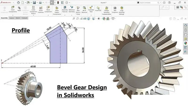
Geometric constraints in powder metallurgy impose size boundaries on bevel gear design. Depending on press tonnage capabilities, diameter limitations typically cap at 150 mm, while overall height stays within 60 mm—achievable using heavy-duty 1,000-ton compaction presses. The aspect ratio must stay within 8:1 to maintain structural integrity during compaction and ejection. These restrictions stem from press capacity and the vertical compaction process inherent to powder metallurgy manufacturing.
Face width presents another critical limitation. Most compaction presses restrict face width to well under 3 inches. Frictional losses between powder and die walls create density gradients across the face width. The lowest density occurs at the mid-point. Larger face widths magnify these density variations and cause dimensional inconsistencies during sintering and heat treatment that lead to distortion, especially when you have larger gears.
Spiral Bevel Gear vs Straight Bevel Gear Design Feasibility
Straight bevel gears prove more feasible for powder metallurgy production than spiral configurations. The vertically oriented compaction process produces dense teeth in straight bevel gears since teeth arrange closer to the pressing direction. Spiral bevel gears have teeth oriented at angles to the centerline. This makes the vertical compaction process less effective and produces lower tooth density.
Tooth Profile Limitations and Draft Angle Considerations in PM
Wall thickness must meet a minimum of 1.52 mm to ensure tooling durability. Boss features require a minimum 12° draft on each side to ensure smooth ejection from the die. Engineers should avoid sharp corners to prevent stress concentrations that cause die breakage. Chamfers at 30° or 45° angles replace radii in part design, as radii result in burrs during compaction and increase tooling costs.
Pressure Angle and Face Width Design Parameters
Standard pressure angles for bevel gears include 20° and 25°. The 20° pressure angle serves as the industry standard, while 25° pressure angles suit designs with 12 or 13 teeth. Face width should not exceed one third of the cone distance to prevent excessive proportion differences between inner and outer tooth ends.
Material Selection and Mechanical Properties for Gear Design
Common Alloys: Iron-Nickel, Copper Steels, and Stainless Steel (17-4PH)
Material choice determines sintered bevel gear performance under different loads. Iron-based alloys are the foundations for most powder metallurgy gear applications. Carbon additions increase hardness for moderate loads. Nickel steel combinations deliver excellent strength-to-weight ratios, and chromium improves wear resistance and hardenability. Adding 2% to 4% nickel substantially improves ductility and impact resistance, achieving 8-18 J. Chromium combined with molybdenum redefines tensile strength limits up to 1,282 MPa after heat treatment.
17-4PH stainless steel provides a precipitation-hardening alternative for corrosive environments. This martensitic alloy achieves 40-44 HRC hardness through age hardening and maintains corrosion resistance. Sintered 17-4PH parts reach densities of 6.8 to 7.3 g/cm³, with H900 aging producing tensile strengths approaching 1,310 MPa.
Density Requirements: 6.8–7.4 g/cm³ Performance Trade-offs
Sintered bevel gears exhibit density ranges between 6.8-7.4 g/cm³ that directly affect mechanical properties. Gear teeth have about 50% lower impact resistance and 33% lower contact fatigue strength compared to wrought steel gears due to porosity. But sinter-hardened materials with 7.5 g/cm³ density can match the endurance limits of quenched and tempered wrought steel.
Densities above 7.4 g/cm³ make the material form a case-carburized layer. This provides a hard martensitic surface region and a non-martensitic core. Standard cold pressing produces 6.9-7.1 g/cm³ density for machinery gears. Warm compaction reaches 7.2-7.3 g/cm³. Warm compaction demonstrates a 30% increase in tooth strength compared to conventional compaction.
Surface Hardness vs Core Strength in Sintered Materials
Balancing surface durability with core toughness is critical for bevel gear design. Sintered gears achieve hardness levels ranging from 45 to 70 HRC. Surface hardness resists wear and pitting while core strength absorbs shock loads. Heat-treated sintered metal gears fall between 53-58 HRC, making them suitable for moderate-load applications.
Surface densification creates a composite structure with a pore-free case and porous core. Rolling contact fatigue strength of rolled powder metallurgy steel reached 96% of case-hardened wrought steel strength. Gas carburized, gear-rolled 7.5 g/cm³ core dense gears with 0.3 mm densification depth reached 1,200 MPa pitting resistance.
Heat Treatment and Secondary Operations for Boosted Durability
Carburizing increases surface hardness by introducing carbon into the gear material at elevated temperatures in carbon-rich atmospheres. This process produces favorable compressive stresses and results in 15-20% improvement in rotating bending fatigue properties. Case depths vary from 0.005 to 0.325 inches depending on application requirements.
Sinter-hardening reduces distortion that comes with conventional quench-and-temper heat treating. Cooling in the sintering furnace achieves desired mechanical properties without losing dimensional accuracy. Shot peening after common heat treatment increases gear tooth root strength up to 1,400 MPa. Nitriding, performed at lower temperatures between 500°C and 600°C, produces hard, wear-resistant surfaces with excellent fatigue strength and minimal deformation.
Selection Criteria: When to Specify Sintered vs Machined Bevel Gears
Load Capacity Comparison: Sintered vs Traditional Bevel Gears
Modern sintered bevel gears achieve 80 to 90 percent of the strength that equivalent solid steel gears have. Standard sintered materials reach 85-91% of comparable machined steel tensile strength, and advanced sinter-hardened grades approach 95% performance. But torque capacity remains capped at 300 Nm due to porosity. Sintered gear teeth exhibit 50% lower impact resistance and 33% lower contact fatigue strength than wrought steel options.
Cost-Performance Break-Even Analysis by Production Volume
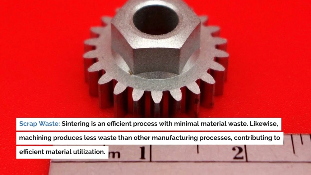
Volume thresholds determine economic feasibility. Simple geometry components break even at 5,000-10,000 units, moderate complexity parts at 1,000-3,000 units, and high complexity designs at 500-1,500 units. Material utilization reaches 95% for sintered gears versus 70% for machined alternatives. Scrap waste drops to 3-5% with powder metallurgy compared to 40-60% for traditional machining.
Design Limitations Engineers Must Account For
Size constraints limit sintered bevel gears to 5-10mm minimum diameter up to 300mm maximum. Density becomes uneven beyond 50mm and causes dimensional inconsistencies. Face width restrictions remain under 3 inches for most compaction presses.
How to Partner with PM Manufacturers for Custom Bevel Gear Prototypes
Manufacturers with advanced powder metallurgy techniques custom alloy blending to achieve specific density, hardness, or lubrication characteristics. Engineering collaboration will give sintered bevel gear design that meets load, lifecycle, and tolerance requirements.
Engineering collaboration ensures your sintered bevel gear design meets load, lifecycle, and tolerance requirements. When transitioning from design to mass production, partnering with an experienced manufacturer for custom sintered bevel gears ensures your drawings are fully optimized for cost and manufacturability.
Conclusion
Sintered bevel gears offer engineers a budget-friendly alternative to machined options when production volumes justify tooling investments. The powder metallurgy process delivers 95% material utilization and achieves 80-90% of solid steel strength. This makes these gears suitable for moderate-load applications. But engineers must account for size limitations, density constraints, and torque capacity restrictions. The selection decision hinges on balancing production volume and load requirements against manufacturing economics and geometric feasibility.