
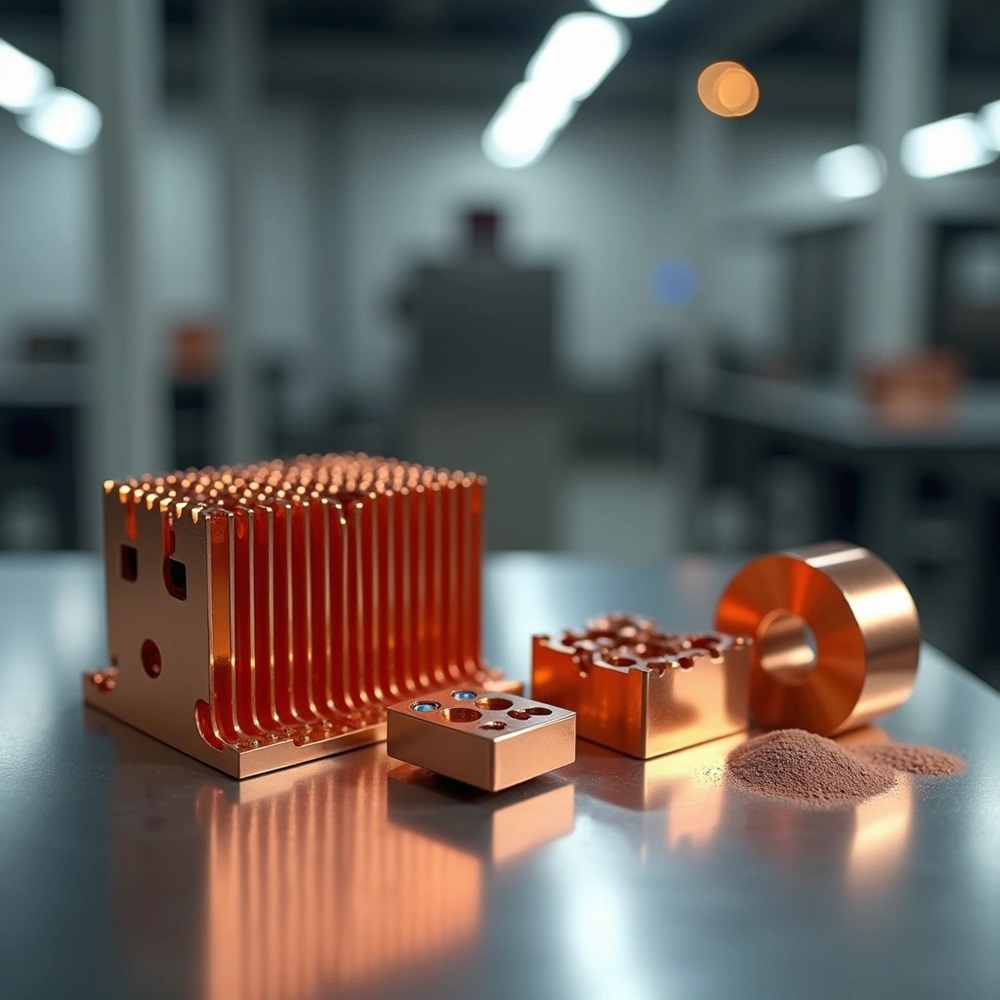
Copper injection molding produces components with thermal conductivity reaching 320 to 400 W/mK. This makes it vital for applications that demand high heat dissipation and electrical performance. This manufacturing process, also known as copper metal injection molding (CuMIM), allows production of complex copper parts with intricate geometries. Traditional machining cannot achieve these efficiently. In fact, manufacturers have already delivered more than 5 million copper parts globally using this technology. Pure copper MIM and copper alloy variations serve critical roles in power electronics and electric vehicles, especially for copper heat sinks MIM and high-current connectors. This piece gets into the complete copper MIM process, material properties, industrial applications, and economic considerations when comparing CuMIM to conventional manufacturing methods.
Pure Copper MIM: Process Steps and Metallurgical Properties
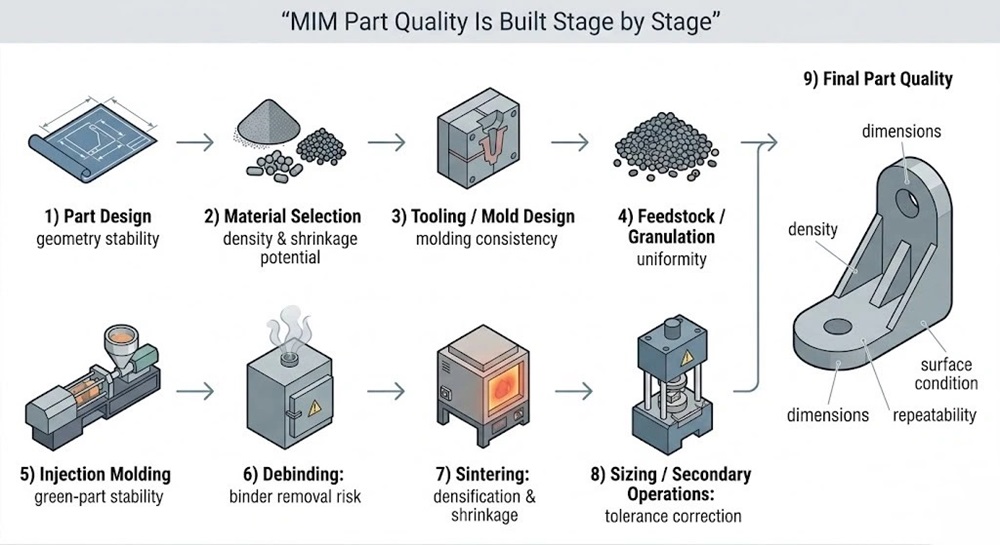
Powder Selection & Feedstock Formulation
The copper MIM process begins with fine copper powders produced through gas atomization in nitrogen, with particle size distributions ranging from 90% below 22 µm to 90% below 31 µm. Manufacturers prioritize minimizing oxygen pickup during atomization. Oxygen levels are measured between 0.055% and 0.078% for high-conductivity copper powders. Spherical particle shapes and broad size distributions make particle packing easier in green bodies and enable high-density sintered materials.
These copper powders are combined with proprietary wax-polymer binder systems at optimized powder loadings of 60 vol% to create feedstock formulation [62]. Commercial feedstocks may contain 93.5 wt% copper mixed with polyethylene glycol (PEG) and wax. PEG provides flexibility during molding while wax serves as the backbone binder. Particle sizes in feedstock granules range from 2 to 20 µm. The powder-to-binder ratio can reach 95:5 (mass%) for optimal MIM products.
The Critical Two-Stage Debinding Phase: Solvent & Thermal
Debinding remains the most time-intensive phase in pure copper MIM and determines final part quality Solvent debinding extracts the primary binder component by immersing samples in water at room temperature, 40°C, or 60°C for 12 hours. Drying follows at 100°C for 2 hours. This process creates interconnected pore networks that make subsequent binder removal easier.
Thermal debinding follows at controlled heating rates of 1°C/min up to 500°C or 730°C, with isothermal holding for 1 hour. Total weight loss during both debinding stages reaches about 6.5%. Direct thermal debinding without the solvent stage results in crack formation and swelling due to excessive polymer extraction.
Atmosphere-Controlled Sintering in Dry Hydrogen and High Vacuum
Sintering occurs in reducing atmospheres of dry hydrogen or He-4%H2 to prevent oxide formation at particle surfaces. Combined debinding and sintering furnaces operate at maximum temperatures between 1030°C and 1050°C. Heating rates of 4°C/min with isothermal holding times of 3 hours achieve optimal densification.
Sintered relative densities consistently reach between 95.0% and 97.0% depending on powder particle size and atmosphere purity. Maintaining an oxygen-free reduction environment is paramount to achieving full density.
Thermal and Electrical Conductivity Measures (320–380 W/mK & 80-90% IACS)
Sintered copper MIM components achieve thermal conductivity values of around 380 W/mK [62], with commercial parts reaching 320 W/mK. Electrical conductivity approaches 80-90% IACS for chromium coppers and phosphorized copper variants. Optimized pure copper MIM can potentially reach up to 100% IACS after proper sintering.
Copper Alloys for MIM: Characteristics and Sintered Densities
Brass MIM (CuZn): Enhancing Flowability and Corrosion Resistance
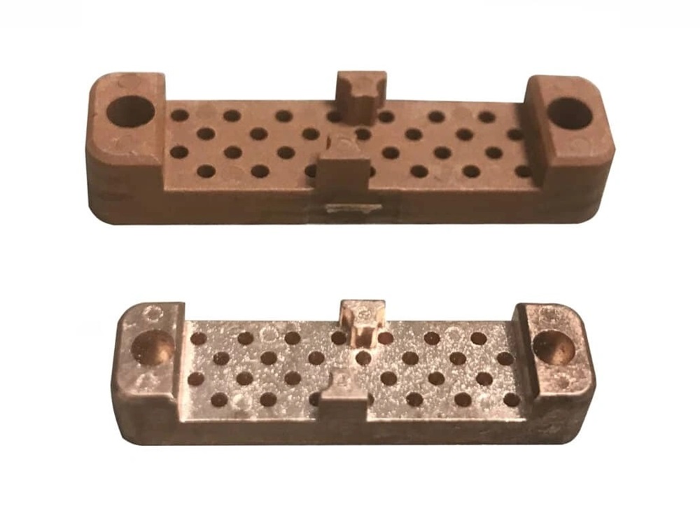
Brass MIM utilizes copper-zinc alloy powder matrix formulations (such as CuZn30 or CuZn37) to deliver excellent fluidity during injection molding and superior mechanical strength post-sintering. Sintered density for brass MIM components ranges from 8.4 to 8.7 g/cm³. The addition of zinc lowers the melting temperature, improves corrosion resistance in marine and industrial environments, and enhances surface machinability for secondary thread-tapping or polishing operations.
Bronze MIM (CuSn): Formulations for Mechanical Wear and Ductility
Bronze alloys (such as CuSn10) in metal injection molding are selected for high-wear environments requiring high tensile strength and ductility. Sintered densities typically fall between 8.5 and 8.8 g/cm³. Bronze MIM components exhibit exceptional wear resistance, self-lubricating qualities when porous, and good fatigue resistance. Common uses include self-lubricating bearings, bushings, and mechanical lock hardware where structural integrity under friction is crucial.
Tungsten-Copper MIM (CuW): Managing High Density (11.5–16.0 g/cm³) and Thermal Management
Tungsten-Copper (CuW) composite MIM blends tungsten powder with copper to synthesize materials with tailored thermal expansion coefficients (CTE) and high thermal dissipation. Due to tungsten’s extremely high density 19.3 g/cm³, industrial CuW alloys achieve sintered densities ranging from 11.5 to 16 g/cm³, depending on the tungsten ratio (e.g., CuW70 to CuW90). CuW MIM provides low thermal expansion matching semiconductor substrates (like GaAs or GaN) while offering high thermal performance, making it the premier material choice for RF packages, laser diode submounts, and high-voltage electrical contacts.
Industrial Applications: Heat Sinks, Connectors, and Custom Parts
Power Electronics: Intricate Pin-Fin Heat Sinks & Spreaders
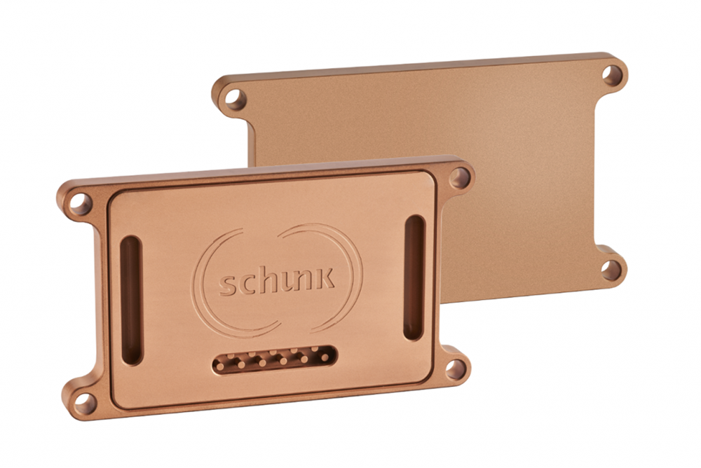
Copper metal injection molding makes unconventional heat sink designs possible for power electronics, optoelectronics and automotive applications where conventional manufacturing faces geometric limitations. Pin-fin configurations allow airflow from multiple directions and create turbulence effects that boost thermal transfer rates. AMT has delivered more than 5 million copper parts worldwide using CuMIM technology. Components achieve thermal conductivity of 320 W/mK. These complex copper parts manufacturing solutions permit electronic components to mount onto the copper structure and dissipate heat through integrated pathways at the same time.
Heat spreaders manufactured through copper injection molding transfer heat faster from concentrated sources like high-power processors and LEDs to cooler device regions. The process creates thin, efficient designs with precise geometries that fit compact electronics without adding bulk. Copper’s malleability combined with MIM precision makes custom-shaped spreaders possible that maximize thermal contact and improve heat dissipation performance.
Electric Vehicles (EVs): High-Current Terminals and Battery Connectors
Battery interconnection systems in electric vehicles just need connectors capable of handling sustained currents up to 600 amps during DC charging cycles and higher peak levels during acceleration. Thermal management becomes critical as high-current flow generates heat that accelerates component aging. Pure copper MIM and copper alloy injection molding produce terminals with minimal heat loss to maximize electricity transfer within battery packs. These high electrical conductivity copper parts must operate across temperature ranges from -40°C to +75°C. Connection points function at or above +150°C under high-load conditions.
Optoelectronics & Semiconductors: Laser Diode Submounts
Laser diode packaging requires submounts with thermal conductivity matching the coefficient of thermal expansion (CTE) to fragile gallium arsenide materials. Tungsten-copper submounts provide thermal conductivity from 180 to 230 W/mK with CTE values of 6.5 to 9.0 ppm/°C that match laser die specifications. Advanced formulations push tungsten copper thermal conductivity to around 320 W/mK and then bond to pure copper or thermoelectric coolers for advanced heat dissipation during high-power laser operations.
Copper MIM vs. CNC Machining: Technical & Economic Feasibility
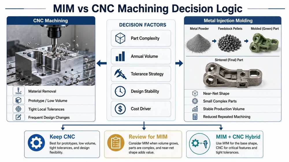
Tooling Investment and Amortization vs. CNC Setup Costs
Manufacturing engineers face different cost structures when selecting between copper metal injection molding and CNC machining. MIM requires upfront mold investment ranging from USD 5,000 to USD 50,000 based on cavity count and complexity. Advanced multi-cavity tools reach USD 100,000+. CNC machining eliminates tooling costs but incurs programming expenses of USD 200 to USD 2,000 per batch. Machine time rates span USD 40 to USD 150 per hour based on axis configuration.
Material Conservation: Eliminating High-Value Copper Scrap in High-Volume Runs
Material utilization rates favor copper injection molding at production scale. The process achieves material efficiency exceeding 95% with feedstock recycling. CNC machining generates 60-80% waste for complex geometries. A 20-gram pure copper part costs USD 0.80 to USD 2.50 in MIM versus USD 3.00 to USD 8.00 in CNC at volumes above 50,000 units.
Geometric Freedom: Blind Holes, Undercuts, and Internal Fluid Channels
MIM creates complex copper parts with features that standard milling operations cannot access. The process molds undercuts, blind holes, and internal channels directly. This is especially advantageous for components requiring cross-holes at non-orthogonal angles. CNC faces limitations with deep narrow pockets and curved internal channels that require specialized EDM processing.
Determining the Economic Break-Even Volume for Copper MIM (e.g., 5000+ Parts)
Break-even analysis identifies crossover points between 3,000 and 15,000 parts based on geometry complexity. Production volumes exceeding 10,000 units make pure copper MIM economically attractive. Cost advantages reach 30-70% for complex geometries under 100 grams.
Conclusion
Copper metal injection molding delivers thermal conductivity reaching 320 to 400 W/mK and enables complex geometries that traditional machining cannot achieve. Material efficiency exceeds 95%, coupled with major cost advantages at production volumes above 5,000 units. Applications span power electronics heat sinks and electric vehicle connectors, along with semiconductor submounts where precision and thermal performance are critical. JHMIM’s 18,000+ square meter facility in China is backed by 150+ skilled technicians and sintering equipment. It delivers high-density copper components that solve tight-tolerance manufacturing challenges for global industries.
FAQs
Q1. Is copper suitable for metal injection molding processes? Yes, copper is highly suitable for metal injection molding. Its excellent thermal conductivity and malleability make it an ideal material for MIM applications. Copper MIM can produce parts with thermal conductivity reaching 320-400 W/mK, making it essential for heat dissipation and electrical performance applications in power electronics, electric vehicles, and semiconductor industries.
Q2. What dimensional tolerances can be achieved with copper metal injection molding? Copper metal injection molding typically achieves dimensional tolerances of ±0.3%. For applications requiring tighter tolerances, additional machining operations may be necessary. The process excels at producing complex geometries with features like blind holes, undercuts, and internal channels that would be difficult or impossible to manufacture efficiently through conventional methods.
Q3. At what production volume does copper MIM become economically viable compared to CNC machining? Copper MIM typically becomes economically attractive at production volumes exceeding 5,000 to 10,000 units annually. The break-even point usually falls between 3,000 and 15,000 parts depending on component complexity. At higher volumes, copper MIM can offer cost advantages of 30-70% for complex geometries under 100 grams compared to CNC machining.
Q4. What are the key steps in the copper metal injection molding process? The copper MIM process involves four main stages: powder selection and feedstock formulation using fine copper powders mixed with binder systems, injection molding of the feedstock into molds, a critical two-stage debinding phase (solvent and thermal), and atmosphere-controlled sintering in dry hydrogen or high vacuum at temperatures between 1030-1050°C to achieve final densification.
Q5. What material efficiency advantages does copper MIM offer over traditional machining? Copper MIM achieves material efficiency exceeding 95% with feedstock recycling capabilities, while CNC machining typically generates 60-80% waste for complex geometries. This significant reduction in material waste is particularly valuable when working with high-value copper, making MIM more cost-effective and environmentally sustainable for high-volume production runs.