MIM tooling has revolutionized the manufacturing of precision metal components with complex geometries. Metal injection molding (MIM) provides exceptional capabilities to produce intricate, high-performance parts with remarkable precision at affordable costs. Manufacturers can now create complex-shaped metal components and achieve material utilization rates of up to 98%, which substantially reduces waste compared to traditional methods.
MIM’s process combines plastic injection molding’s design flexibility with metal parts’ superior mechanical properties. The technology has become a standard in industries of all sizes, from medical devices and electronics to firearms and automotive, because it helps produce small, high-precision components in large quantities. MIM manufacturing delivers parts with tight tolerances and works with a variety of metals, including stainless steel, titanium, and other high-performance alloys. The process’s superior surface quality and net-shape capabilities make it invaluable for precision tools and hardware applications that demand exact dimensional accuracy and specific material properties.
Precision Tooling Requirements in MIM Manufacturing
MIM tooling quality sets the foundation for successful metal injection molding processes. Every production stage needs precise specifications to meet exact requirements.
Dimensional Tolerance Capabilities in MIM
Dimensional accuracy stands at the heart of MIM manufacturing. MIM processes achieve tolerances between ±0.3% and ±0.5% of nominal dimension. Manufacturers can reach even tighter tolerances of ±0.3% for specific features through optimized processes. The tolerance capabilities change with feature size:
- ±0.03 mm for features below 3 mm
- ±0.05 mm for features between 3-6 mm
- ±0.08 mm for features between 6-15 mm
Tooling quality, shrinkage compensation, and feedstock formulation all play a role in achieving these precision levels. Tooling issues cause 70% of MIM defects, which shows how proper tool design affects dimensional accuracy.
Surface Finish Quality for Cutting and Forming Tools
Tool surface quality shapes the final product’s performance. MIM technology delivers excellent surface finishes with Ra values under 0.8 micrometers. Metal parts show a smooth finish after sintering with a root mean square roughness of around 32.
Surface characteristics matter even more for cutting tools and similar applications. Tool steel MIM parts show as-sintered surface roughness between 1-3 μm Ra. Secondary finishing can improve this to 0.2-0.8 μm Ra. A smooth tool surface creates better-finished molded parts and cuts down post-processing work.
Material Hardness Achieved Post-Sintering
The material’s post-sintering properties determine how well a tool performs. MIM parts reach 95-98% of theoretical density after sintering. Hot isostatic pressing can push this density up to 99%.
Hardness plays a vital role in tool steel applications. MIM tool steel components match traditionally forged tool steels with surface hardness values of 58-65 HRC after heat treatment. Different alloys provide varying hardness levels. MIM H11 with master alloy approach gives 54 HRC after sintering. T15 can hit 65 HRC with optimized heat treatment.
These outstanding material properties make MIM manufacturing perfect for precision tools that need both complex shapes and top-tier mechanical performance.
MIM Process Adaptations for Tool and Hardware Production
The MIM process needs special feedstock compositions and processing parameters to work well for tool and hardware applications. These technical changes improve the performance that high-wear environments just need.
Feedstock Formulation for High-Wear Applications
Creating tool steel feedstock requires careful material selection to get the best mechanical properties. Most MIM tool steel formulations employ a multicomponent binder system that has:
- High-density polyethylene (HDPE) that gives structural integrity and shape retention
- Paraffin wax that improves flowability at processing temperatures
- Specific ratio adjustments that keep rheological stability
Research shows that 50 vol.-% HDPE content works best for MIM processing of tool steels. The maximum metal powder loading reaches about 70 vol.-%, based on torque measurement analyses. Loading more metal creates feedstock that’s too viscous to inject, while too little metal leads to weak green parts.
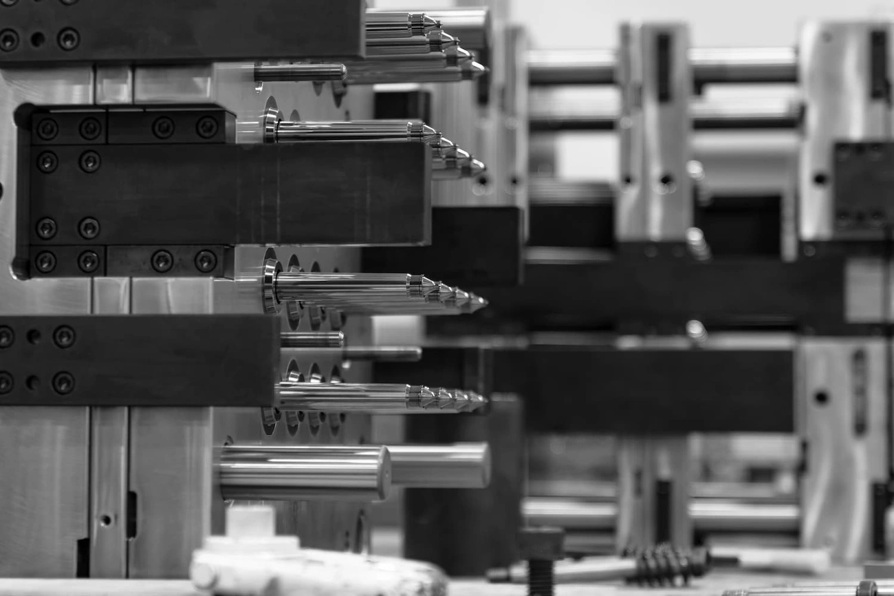
Injection Molding of Complex Tool Geometries
Making complex tool components through MIM requires exact control during injection. Tool steel feedstock needs specific temperature profiles after pelletizing to reach remelt conditions before injection. The process must balance good flowability with the right viscosity to avoid defects in complex shapes.
Tool design has sections for features like internal and external threads, undercuts, and complex profiles. Proper gating becomes vital for thick cross-sections found in tool applications. The gate works best at the thickest area, so material flows from thick to thin sections.
Debinding Techniques for Thick-Walled Tool Parts
Thick-walled tool components create unique debinding challenges. Most manufacturers use a two-stage approach:
The first stage uses solvent debinding to remove primary binder components (usually wax) at about 60°C. This creates a porous network without distortion. The second stage uses thermal debinding between 400-900°C to remove remaining polymer binders. This approach prevents defects like cracking that happen with quick binder removal from thick sections.
Sintering Profiles for Tool Steels like M2 and D2
M2 tool steel’s sintering window is quite narrow – just 13°C between 1245-1258°C. This is a big deal as it means that you need multi-zone sintering furnaces with perfect temperature control. The material densifies through supersolidus liquid-phase sintering, with rapid consolidation happening once it passes the solidus temperature.
Pre-alloyed M2 powders reach over 98% density at 1220°C and full density at 1240-1250°C. The sintering atmosphere changes the final properties a lot. Vacuum sintering helps achieve full densification by removing gases from pores. N2-rich atmospheres can make the sintering window wider by forming carbonitrides that pin grain boundaries during the process.
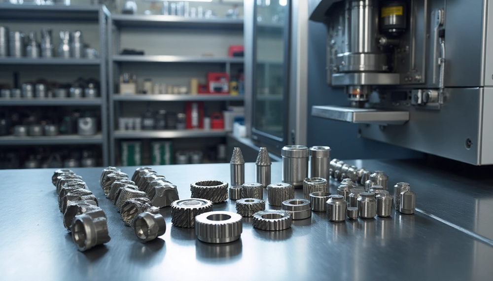
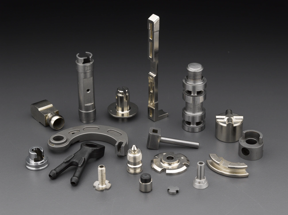
Common MIM Applications in Precision Tools
Metal injection molding creates complex precision tool components in a variety of industries. The MIM process’s versatility makes it perfect for high-performance applications.
Punches and Dies for Sheet Metal Forming
MIM technology produces precise male punch components and female die cavities that are crucial for sheet metal forming operations. These components handle critical functions such as material deformation, cutting, piercing, and bending. The MIM manufacturing process creates complex die geometries with intricate contours that traditional machining cannot achieve.
Precision Gears and Micro-Splines
MIM manufacturing creates micro gears with module sizes as small as 0.02. These high-precision components reach dimensional accuracy of ±0.1% and surface roughness values as low as Ra 0.43 μm. The process excels at creating special gear designs like intermittent, eccentric, and different module stepped gears.
Cutting Inserts and Drill Bits
MIM technology’s drill bits show exceptional hardness values—reaching 97.9 HRA for milling components and 86.0 HRA for driving components. Cutting inserts benefit from precise geometries and consistent material properties through metal injection molding.
Torque Tools: Sockets and Wrenches
MIM-produced torque components deliver optimal accuracy for applications from aerospace to wind energy. These precision-engineered parts combine durability with superior ergonomics.
Tool Handles and Ergonomic Grips
MIM’s handle production incorporates intricate ergonomic contours, anti-slip textures, and integrated features that traditional manufacturing cannot match. These components maintain exceptional strength with >98% material density.
Design and Production Considerations for MIM Hardware
Design principles are the lifeblood of successful hardware production through metal injection molding. Your part’s performance, budget-friendly manufacturing, and overall feasibility depend on the following crucial parameters.
Wall Thickness Guidelines for Structural Hardware
MIM hardware components work best with a wall thickness between 0.040″ to 0.120″ (1-3mm). Walls thinner than 0.5mm might break during ejection. Thick walls beyond 4-5mm will slow down cycle times and waste materials. The part’s uniform thickness reduces molding defects, looks better, and improves dimensional tolerances. You’ll need gradual transitions between sections if different thicknesses can’t be avoided. This prevents stress concentration points from forming.
Undercut and Draft Angle Management in Mold Design
MIM components don’t usually need draft angles, unlike plastic injection molding. A minimal 0.5-degree draft helps with ejection for features with high aspect ratios, like thin wall sections or long core pins. Complex geometries can work with undercuts through specialized mold design that uses collapsible cores or sliders. External undercuts are easier to work with than internal ones, which need more advanced tooling solutions.
Post-Sintering Machining for Tight Tolerances
MIM achieves tolerance averages of ±0.3%, but critical features might need secondary operations for tighter specs. The most common post-sintering processes include machining, tapping, drilling, and grinding. These operations target specific features like threads, undercuts, or grooves that would need expensive tooling otherwise. Notwithstanding that, secondary processing raises production costs. The core team should minimize these needs through careful original design.
Shrinkage Compensation in Mold Cavity Design
MIM parts shrink about 20% during sintering. So mold cavities need proportional oversizing to account for this dimensional change. Feedstock composition, mold design, and processing parameters affect shrinkage. Uniform wall thickness helps parts shrink evenly. The part’s orientation and support during sintering also prevent distortion from gravity as parts soften at high temperatures.
Conclusion
Metal Injection Molding revolutionizes manufacturing for precision tools and hardware applications. This advanced technology combines plastic injection molding’s design flexibility with metal components’ superior mechanical properties. MIM technology boasts material utilization rates up to 98%, which cuts waste compared to standard manufacturing methods.
MIM components showcase remarkable dimensional accuracy with tolerances from ±0.3% to ±0.5% of nominal dimensions. The surface finish quality adds more value as MIM delivers Ra values under 0.8 micrometers. Tool steel components can reach hardness values between 58-65 HRC after heat treatment, matching traditional forged tool steels.
The process shows its versatility in a variety of industries. Complex geometries and consistent materials make it perfect for precision components like punches, dies, micro-gears, cutting inserts, and ergonomic tool handles. Manufacturers can meet high-wear environment requirements through specialized feedstock formulations, careful injection molding parameters, and optimized sintering profiles.
Design plays a key role in successful implementation. Wall thickness, undercut management, and shrinkage compensation shape the quality of MIM components. A well-planned original design reduces the need for post-sintering operations, even when dealing with the tightest tolerances.
JH MIM stands out with its 20 years of experience in metal injection molding. Their 18,000-square-meter facilities house advanced equipment and 150 skilled workers. They serve global customers with precision-engineered products, making them China’s leading Metal Injection Molding manufacturer.
MIM technology’s ongoing advancement promises better capabilities for precision tools and hardware. More manufacturers now see the benefits of complex geometries, material efficiency, and exceptional mechanical properties. This makes MIM a pioneering force in precision component manufacturing.
Key Takeaways
MIM technology revolutionizes precision tool manufacturing by combining plastic injection molding flexibility with superior metal properties, achieving up to 98% material utilization while reducing waste significantly.
• MIM achieves exceptional precision with tolerances of ±0.3% to ±0.5% and surface finishes below 0.8 μm Ra • Tool steel components reach 58-65 HRC hardness after heat treatment, matching traditionally forged materials • Complex geometries like micro-gears, cutting inserts, and ergonomic handles are producible in high volumes • Proper wall thickness (1-3mm) and shrinkage compensation (20%) are critical for successful MIM hardware design • Specialized feedstock formulations and controlled sintering profiles enable high-wear tool applications
MIM’s ability to create intricate, high-performance components with minimal waste makes it the preferred choice for manufacturers seeking cost-effective precision tooling solutions across automotive, medical, and industrial sectors.
FAQs
Q1. What are the main advantages of using MIM for precision tools and hardware? MIM combines the design flexibility of plastic injection molding with superior metal properties, achieving up to 98% material utilization and reducing waste. It allows for complex geometries, high precision, and excellent mechanical properties in high-volume production.
Q2. How precise are components manufactured using MIM technology? MIM components typically achieve dimensional tolerances ranging from ±0.3% to ±0.5% of nominal dimensions. Surface finishes can be as smooth as 0.8 micrometers Ra, and after heat treatment, tool steel parts can reach hardness values of 58-65 HRC.
Q3. What types of precision tools can be produced using MIM? MIM is suitable for producing a wide range of precision tools, including punches and dies for sheet metal forming, micro-gears and splines, cutting inserts, drill bits, torque tools like sockets and wrenches, and ergonomic tool handles and grips.
Q4. What are the key design considerations for MIM hardware? Important design factors include maintaining optimal wall thickness (typically 1-3mm), managing undercuts and draft angles, compensating for shrinkage (usually around 20%), and considering the need for post-sintering machining for extremely tight tolerances.
Q5. How does MIM compare to traditional manufacturing methods for precision tools? MIM offers advantages in producing complex shapes and intricate details that would be difficult or impossible with traditional machining. It provides excellent material properties, high production efficiency, and cost-effectiveness for high-volume production, making it increasingly preferred for precision tooling across various industries.