
Tin Electroplating for Metal Components: Process Guide and Selection Criteria
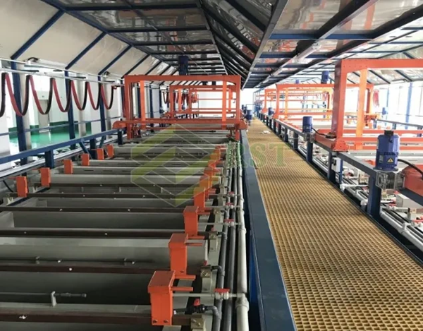
Tin electroplating is a core surface finishing process that deposits a thin, protective tin layer onto metal substrates through electrochemical reduction. Designed to enhance solderability, lower electrical contact resistance (<5 mΩ), and protect against oxidation according to ASTM B545 standards, this process is widely applied across electronics, automotive terminals, and precision powder metallurgy (PM/MIM) components.
Understanding Tin Electroplating for Metal Components
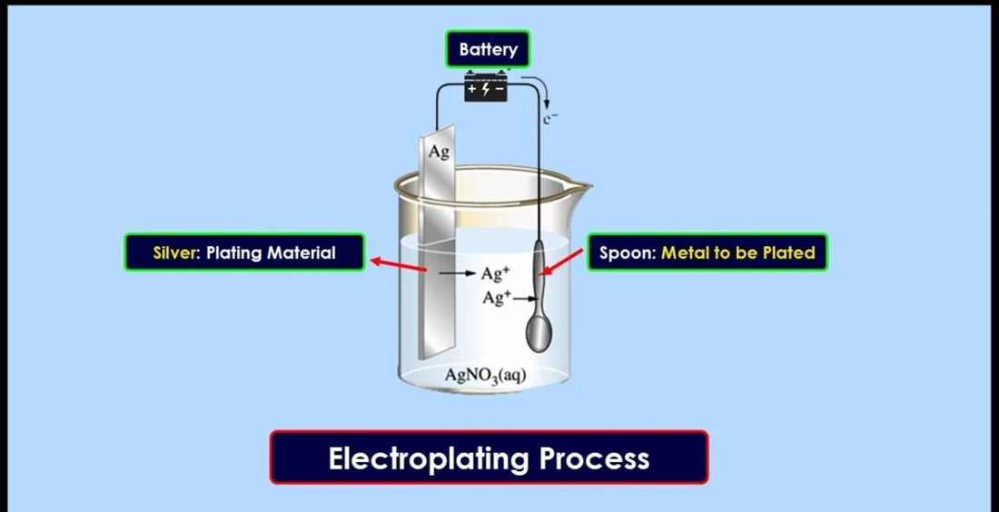
What is Tin Electroplating?
Tin electroplating coats metal components via electrochemical deposition, using stannous-based or stannate electrolyte baths.
-
Acidic Baths: Utilize stannous sulfate or methanesulfonic acid for high deposition speed, smooth finishes, and lower energy consumption.
-
Alkaline Baths: Employ sodium stannate solutions to achieve superior throwing power and uniform coverage on complex internal geometries.
-
Substrate Compatibility: Applied across steel, stainless steel, copper, brass, and aluminum parts.
-
Coating Range: Maintained between 0.5 to 25 microns, tailored to specific corrosion and soldering specifications.
Key Technical Properties of Tin Coatings (Contact Resistance, Hardness & Thickness)
-
Low Contact Resistance: Pure tin deposits maintain stable, low contact resistance (5–15 milliohms) for reliable electrical transmission in connector assemblies.
-
Vickers Hardness: Bright tin achieves 10–15 HV, offering light wear resistance. Matte tin ranges from 5–8 HV, providing higher ductility for crimping.
-
Thickness Standards: Requires 2.5–5 microns for standard solderability, and 8–15+ microns for severe outdoor/industrial corrosion environments.
-
Grain Structure Impact: Fine-grain matte tin yields superior wetting during soldering and lower internal stress, reducing long-term tin whisker risks.
Electroplating vs. Hot-Dip Tinning and Chemical Immersion Tin
-
Tin Electroplating: Operates at room temperature with precise thickness control (0.5–25 µm). Ideal for tight-tolerance precision parts, complex geometries, and heat-sensitive alloys.
-
Hot-Dip Tinning: Immersion in molten tin (230–270°C). Produces thick coatings (8–50 µm) with high bulk processing efficiency, but lacks dimensional precision.
-
Chemical Immersion Tin: Chemical displacement yielding ultra-thin deposits (0.3–1.2 µm). Cost-effective for PCB surface finishes, but offers limited wear and corrosion protection.
Tin Electroplating Process: Step-by-Step OEM Guide
Ultrasonic Cleaning, Degreasing, and Surface Inspection
Proper substrate preparation determines coating adhesion and long-term performance. Surface contaminants such as oils, grease, oxides, and particulate matter must be removed before electroplating metal components. The cleaning sequence begins with mechanical or chemical pre-cleaning. Precision ultrasonic treatment comes next.
Ultrasonic cleaning gets high-frequency sound waves that create cavitation bubbles in the cleaning solution. These microscopic bubbles collapse instantly and release energy that dislodges contaminants from complex geometries, blind holes, and recessed features. The process operates in alkaline, acidic, or solvent-based solutions at temperatures between room temperature and 70°C.
Electroplating steel and copper substrates requires electrolytic degreasing after ultrasonic treatment. The component submerges in a hot alkaline solution at 60°C under 4V voltage for one minute. Cathodic electrolytic degreasing removes residual oils trapped in surface irregularities that mechanical cleaning cannot reach. Heavy-duty alkaline cleaners containing silicates and sequestering agents handle stubborn contamination from drawing compounds and corrosion preventatives.
Acid Activation and Surface Pre-Treatment
Metal surfaces form thin oxide layers when exposed to atmospheric conditions. These passive films interfere with tin deposit adhesion. Acid activation removes nascent oxides immediately before plating bath immersion. Steel components receive dilute hydrochloric acid treatment, while copper and brass undergo sulfuric acid pickling at 10% concentration for 30 seconds.
Pickling provides thorough cleaning and activation by dissolving the oxide layer and exposing pure base metal. The acid concentration and immersion time vary by substrate composition. Components need immediate water rinsing and transfer to the plating bath after acid activation to prevent oxide reformation.
Electrolytic Tin Plating Bath Setup (Acidic vs. Alkaline Electrolytes)
Acidic tin plating baths employ stannous sulfate or methanesulfonic acid formulations. These systems operate at pH 0.5-2.0 and provide faster deposition rates compared to alkaline solutions. Acid baths produce uniform coating distribution but may struggle with complex geometries that need high throwing power.
Alkaline electrolytes employ sodium stannate with free hydroxide and cyanide additions. A typical formulation contains 30 g/L tin, 2.5 g/L zinc, 4-6 g/L free hydroxide, and 28 g/L free cyanide, operating at 65°C. Alkaline baths need pH adjustment to 4.5 and temperature control at 60°C for optimal performance. The bath selection depends on substrate material, desired deposit characteristics, and production requirements.
Current Density, Deposition Rate, and Amperage Control
Current density influences deposit morphology, grain structure, and coating uniformity. Optimal ranges fall between 3-5 A/dm² for most applications. Lower current densities at 1.7 A/dm² produce fine-grain deposits with superior surface morphology. Higher densities accelerate deposition but risk surface defects and porosity.
The relationship between current density and coating thickness needs precise time control. Plating at 3 A/dm² for 30 minutes yields approximately 10.6 microns thickness. Deposition rate monitoring prevents over-plating and maintains specification compliance. Temperature maintenance at 60°C and pH stability at 4.5 ensure consistent current efficiency throughout the process.
Post-Plating Rinsing, Passivation, and Thermal Reflow
Components need thorough water rinsing immediately after plating to remove drag-out electrolyte. Passivation treatment comes after rinsing to boost corrosion resistance and prevent surface discoloration. Aqueous solutions containing ammonium phosphate at pH 3-5, applied at 40-60°C for 10-60 seconds, control oxidation and surface twisting after reflow.
Thermal reflow eliminates tin whisker formation risk and improves solderability. The process heats components above tin’s melting point at 260°C for one minute or 450°F. Reflow creates an intermetallic layer, refines grain structure, and produces a smooth, oxide-free surface with boosted electrical conductivity.
Types of Electroplating: Bright Tin Plating vs. Matte Tin
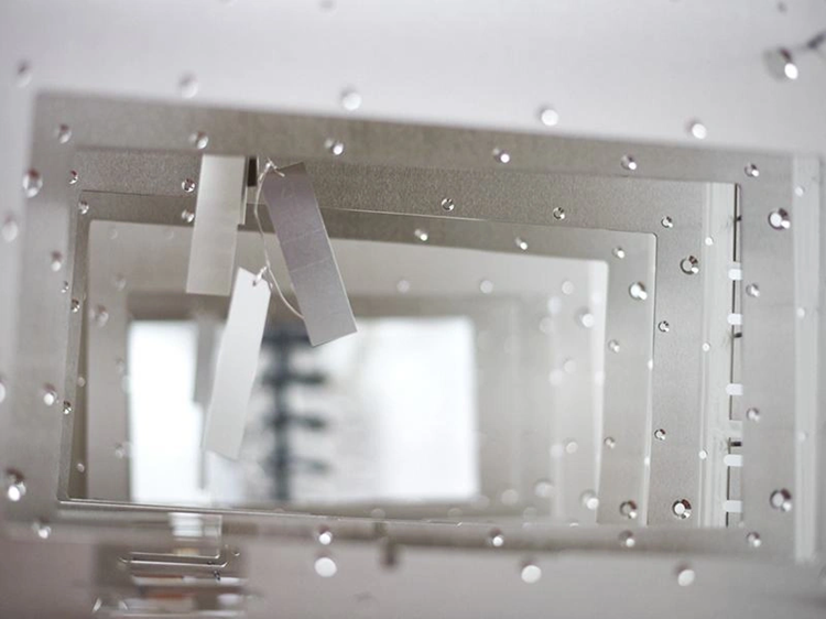
| Performance Metric | Bright Tin Plating | Matte Tin Plating |
| Appearance & Finish | High luster, reflective, mirror-like | Dull, non-reflective, satin gray |
| Organic Additives | High level of brighteners | Zero / minimal organic additives |
| Grain Structure | Extremely fine grain size | Coarser, columnar grain structure |
| Tin Whisker Risk | Higher risk (due to high internal stress) | Very low risk (ideal for electronics) |
| Solderability | Good, but reflow can cause outgassing | Superior (excellent wetting & reflow) |
| Primary Applications | Busbars, terminals, decorative hardware | Semiconductors, IC leads, OEM connectors |
Metal Component Selection & Substrate Compatibility
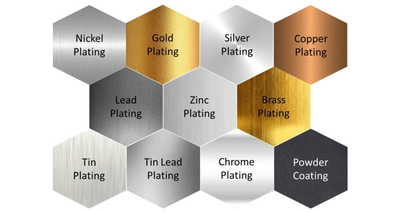
Selecting the right substrate material and understanding its surface compatibility is critical to achieving a durable, high-adhesion tin electroplated layer. Different base metals require tailored pre-treatment chemistries and barrier underplates to prevent intermetallic diffusion, adhesion failure, or porosity-induced internal corrosion.
-
Electroplating Steel and Stainless Steel Components
Steel components are widely electroplated with tin for corrosion resistance and solderability. Standard carbon steels require alkaline degreasing and dilute acid pickling to remove oxide scales prior to plating. For stainless steel substrates, the naturally occurring, passive chromium oxide film prevents direct tin adhesion. A specialized acidic nickel strike (Wood’s Nickel Bath) must be applied first to activate the surface and ensure robust metallurgical bonding.
-
Copper, Brass, and Bronze Alloys (Barrier Layer Requirements)
Copper and its alloys offer excellent inherent conductivity, making them primary candidates for tin-plated electrical terminals, busbars, and connectors. However, direct tin plating on brass or copper can lead to zinc or copper migration into the tin layer over time, forming brittle intermetallic compounds (Cu6Sn5) and increasing tin whisker risks.
Solution: A 1.5 to 3.0 micron copper or nickel underplate must be applied as a diffusion barrier before final tin deposition to maintain long-term solderability.
-
Aluminum Surface Preparation and Zincate Pre-Treatment
Aluminum components offer lightweight advantages but present severe electroplating challenges due to rapid re-oxidation in air and high chemical reactivity. To ensure strong tin adhesion, aluminum surfaces must undergo a dual-zincate immersion process, followed by an electroless nickel or copper strike, before final electrolytic tin plating.
-
Special Consideration: Powder Metallurgy (PM) and MIM Components
Sintered powder metallurgy and Metal Injection Molding (MIM) parts possess inherent microscopic surface porosity. If unsealed, corrosive electroplating bath acids can become trapped inside these pores, leading to internal oxidation, blooming spots, and post-plating failure.
Resin Impregnation / Steam Treatment: PM and MIM components should undergo vacuum resin impregnation or high-temperature steam oxidation prior to plating to completely seal interconnected pores.
Pre-Plating Strike: Applying a dense copper or nickel strike layer ensures 100% surface coverage and airtight sealing across all sintered boundaries.
Selection Criteria: When to Choose Tin Electroplating
Corrosion Resistance Requirements & Salt Spray Test Standards (ASTM B117)
Salt spray testing assesses coating performance under accelerated corrosion conditions. The ASTM B117 standard exposes components to a 5% sodium chloride solution atomized at 35°C. Test duration associates with expected service life and coating thickness. Electroplated zinc-nickel steel parts withstand more than 720 hours in neutral salt spray without red rust. Electroplated zinc with yellow passivation lasts 96 hours without white rust.
Salt spray performance depends on tin plating thickness. Components plated with 8 microns on steel fail within 5 hours under standard test conditions. A 72-hour salt spray life needs increased thickness or barrier layers. Steel substrates need minimum 20-micron coatings to achieve 240-hour resistance. Copper undercoating at 4-5 microns beneath tin layers improves corrosion protection for brass and mild steel components.
Tin’s barrier-layer nature is different from sacrificial zinc coatings. Porosity creates galvanic cells where exposed steel corrodes first. Pore-free coatings need minimum 12-micron thickness on finished substrates. Hot-dipped coatings below 13 microns rarely achieve complete pore-free coverage.
Electrical Conductivity and High-Frequency Solderability Applications
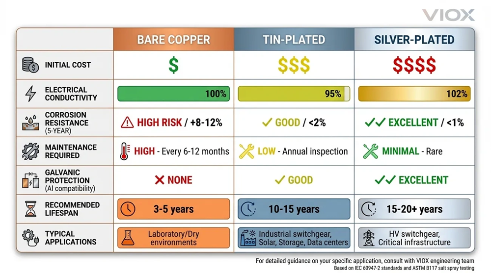
Tin provides sufficient electrical performance for most automotive and electronic circuits despite lower conductivity than precious metals. Tin exhibits about 15% of silver’s conductivity. Contact resistance for tin-plated terminals ranges between 2-5 milliohms, suitable for lighting systems, sensors and general-purpose wiring. Silver-plated terminals achieve 0.1-1 milliohm contact resistance, preferred for high-current applications exceeding 100 amperes.
Solderability represents tin’s main advantage over alternative finishes. Matte tin deposits provide superior solder wetting compared to bright tin due to the absence of organic brightener co-deposits. Wave soldering or reflow processes cause organic additives in bright tin to outgas, which can create voids and weaken solder joints. Matte tin maintains void-free solder connections, making it the standard choice for printed circuit board assemblies and electronic terminals.
Cost-Effectiveness: Tin Electroplating vs. Precious Metal Plating (Gold/Silver)
Economic considerations position tin as the budget-friendly solution for high-volume production. Silver plating costs 3-5 times more than tin[194]. Gold plating commands a 10-20 times premium over tin finishes. Tin-plated terminals cost USD 50-80 per thousand units for automotive applications, while silver ranges USD 150-400 and gold reaches USD 500-1,600 per thousand.
The pricing differential makes tin the default selection for 85-90% of standard passenger vehicle terminals. Silver applications concentrate on starter motors, alternators and battery connections where conductivity justifies the investment. Gold plating restricts to mission-critical signal circuits in engine control units, airbag systems and anti-lock braking sensors.
Industry Standards and Specifications (ASTM B545, MIL-T-10727)
ASTM B545 defines electrodeposited tin coating requirements across five service classes. Class A specifies 2.5-micron thickness for mild conditions, Class B needs 5 microns for moderate indoor exposure, and Class C demands 8-10 microns for severe conditions. MIL-T-10727 superseded by ASTM B545 established military-grade specifications for ferrous and nonferrous metals.
Quick Decision Matrix for Engineers (Bright vs. Matte Selection)
| Application | Recommended Finish | Key Reason |
|---|---|---|
| PCB Assembly | Matte Tin | Superior solderability, no void formation |
| Electrical Contacts (Non-Soldered) | Bright Tin | Low friction, esthetic finish |
| High-Vibration Environments | Matte Tin | Reduced whisker growth risk |
| Esthetic Components | Bright Tin | Mirror-like reflectivity |
Conclusion
Tin electroplating delivers affordable surface protection and solderability for metal components in a variety of industries. Engineers must review corrosion resistance requirements, electrical performance specifications and budget constraints when selecting between tin and precious metal alternatives. The decision matrix between bright and matte finishes depends on application demands, especially for soldered versus non-soldered connections.
Proper substrate preparation, controlled deposition parameters and appropriate post-treatment processes ensure coating performance and longevity. Tin remains the preferred choice for 85-90% of automotive terminals and electronic assemblies. The technical guidance presented here gives manufacturers the tools to optimize coating selection, reduce production costs and maintain quality standards for their component portfolios.
For reliable solderability, a minimum tin plating thickness of 2.5 microns is typically required. For applications demanding robust solder joints and long-term performance, thicknesses between 3-7 microns are recommended. Immersion tin processes usually produce 0.5-2.5 microns, while electrolytic tin plating can achieve 2-10 microns or more depending on the application requirements.
Tin-plated terminals are susceptible to fretting corrosion in vibration environments. The reciprocating friction (typically 10-200 microns) caused by differential thermal expansion between mating metals can damage the tin coating, exposing the base material to oxidation. This results in a significant increase in contact resistance and potential connection failure. For vibration-prone applications, alternative finishes or additional protective measures should be considered.
Matte tin plating is generally preferred for electronic assemblies requiring soldering. Matte tin provides superior solder wetting characteristics because it lacks organic brightener additives that can outgas during reflow or wave soldering, potentially causing voids in solder joints. Bright tin is better suited for non-soldered electrical contacts where esthetic appearance and low friction are priorities.
When tin plating brass components, a nickel underplate layer is essential. This barrier layer prevents zinc from the brass substrate from diffusing into the tin coating, which would otherwise reduce solderability and coating integrity. The nickel layer also slows the formation of intermetallic compounds and improves overall coating performance and durability.
Tin whisker formation can be mitigated through several strategies: applying a nickel or copper-nickel underplate as a barrier layer, using matte tin instead of bright tin processes, performing post-plating thermal treatment (annealing at 120-150°C for several hours), or using tin alloys such as SnBi or SnAg. These methods help relieve internal stresses in the coating that cause whisker growth.