
Sintered Gears
High-strength sintered gears are commonly fabricated from copper-infiltrated sintered steel, achieving relative densities between 90% and 95% of theoretical density with minimal interconnected porosity for quiet and smooth mechanical transmission. Alternatively, sintered gears engineered with controlled surface porosity are oil-impregnated to deliver critical self-lubricating performance and lower sliding wear in continuous-duty applications.
Mechanical properties of sintered gears depend strictly on the selected powder metallurgy route. Recent processing advancements—including warm compaction, high-speed compaction, sinter-hardening, high-temperature sintering, and surface gear densification—now enable high-density (>7.5 g/cm³), highly repeatable gear production at a lower total unit cost than wrought machining.
Sintered Gears vs. Machined Gears
While gear blanks have traditionally been cut, hobbed, and ground from bar stock, conventional machining creates substantial material waste and higher tooling overhead for high-volume automotive programs. Powder metallurgy (PM) technology offers a net-shape manufacturing path that combines high volume repeatability with up to 95% material utilization.
Through high-density compaction, precision sintering, and secondary surface rolling, the powder metallurgy process routinely delivers gear densities exceeding 7.5 g/cm³. These high-density PM gears match or exceed the fatigue and load-bearing performance of forged and machined components in high-stress applications such as synchronizer hubs and clutch gear assemblies.
Core Engineering Advantages of Sintered Gears
Engineers and procurement teams specify sintered gears over machined alternatives due to distinct manufacturing and performance advantages:
- Net-Shape Dimensional Accuracy: Enables complex gear geometries and integrated features (such as dual-gear clusters or stepped splines) with tight tolerances without multi-axis machining.
- Cost-Effective High-Volume Production: Material utilization exceeds 95%. Eliminating secondary operations like hobbing and shaping significantly reduces unit cost and cycle times.
- Tailored Alloy Systems: Blending elemental or pre-alloyed powders (Cu, Ni, Mo, C) allows precise customization of core strength, surface hardness, and impact resistance.
- Inherent Noise Reduction: Controlled internal porosity provides acoustic damping, resulting in quieter tooth meshing compared to fully dense machined steel.
- Reduced Carbon Footprint: Lower processing temperatures relative to full melting and minimal scrap generation make powder metallurgy a energy-efficient manufacturing process.
Mechanical Property Comparison: PM Alloy Systems
Selection of the proper PM material system depends on dynamic load, impact, and surface hardness requirements. The table below compares key mechanical properties between Sintered and Heat-Treated (Quenched & Tempered) states across three common PM alloy grades:
| Property | Copper-Infiltrated Steel (13Cu – 0.8C – Fe Balance) |
Nickel-Steel Alloy (2Ni – 0.5C – 1.5Cu – Fe Balance) |
Low-Alloy Steel (0.4Mn – 0.5Ni – 0.6Mo – 0.5C – Fe) |
|||
|---|---|---|---|---|---|---|
| Quenched & Tempered (871°C) | As-Sintered | Quenched & Tempered (871°C) | As-Sintered | Quenched & Tempered (871°C) | As-Sintered | |
| Density (g/cm³) | 7.3 | 7.3 | 6.8 | 6.8 | 6.7 | 6.8 |
| Ultimate Tensile Strength (MPa) | 790 | 580 | 650 | 350 | 770 | 340 |
| Yield Strength, 0.2% Offset (MPa) | 735 | 395 | 550 | 275 | 705 | 285 |
| Elongation (%) | 0.5 | 3.0 | 0.8 | 1.5 | 0.6 | 1.0 |
| Apparent Hardness | HRC 38 | HRB 89 | HRC 24 | HRB 65 | HRC 29 | HRB 60 |
| Particle Hardness | HRC 58 | — | HRC 40 | — | HRC 44 | — |
| Charpy Unnotched Impact Energy (J) | 8.5 | 13.7 | 13.5 | 9.8 | 12.2 | 8.8 |
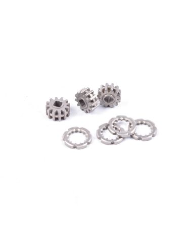
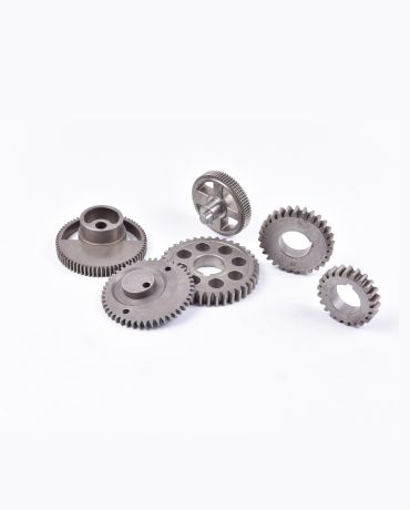
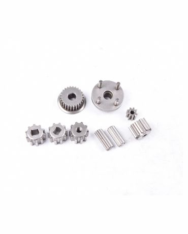
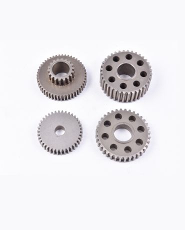
Stainless Steel Sintered Gears
Yes, this is a routine operation for most companies before inquiring.
We have metal 3D printing equipment and can provide sample 3D printing.
3D drawings allow engineers to better understand the structure of the product, and 2D documents can provide more information, including materials, tolerances, surface treatment, etc. More detailed information is conducive to more accurate quotation by engineers.
In the case of detailed inquiry drawings and information, it usually only takes 2-3 days for us to give you a detailed quotation, including the product price and mold price.
After confirming the order, we usually take 5-7 days to prepare the DFM report of the product. After confirmation, we spend 25 days to complete the mold, and provide T1 samples to customers for testing in the following 10-15 days.
If there is a problem with the test, we will re-sample it for free based on the feedback and provide a suitable sample.
MIM products MOQ 2000 PCS
CNC products MOQ 2000 PCS
Alu die casting, MOQ 2000 PCS
PM product MOQ 5000 PCS
Typically, the lead time for processing and submitting samples is 30 days. However, according to the order quantity and special requirements of customers, we can extend or shorten the delivery cycle accordingly.
1-year product warranty
World-class testing equipment
30+QC Workers
Key sizes 100% checking before shipment
ISO9001+IATF16949
Usually T/T is used as the payment method
Mold: 50% deposit, 50% payment after confirming the sample.
Bulk production: 30% deposit, 30% see bill of lading Copy, pay 70% balance.