Oil pumps cause much of the energy loss in automotive systems. They contribute to about 10% of total engine loss and a striking 20% to 30% of total loss in automatic transmission units. These pumps are present in every vehicle, yet they remain among the least technically explored components in the automotive world.
Vehicle performance and efficiency depend heavily on the engine oil pump. The conventional rotor-type oil pumps work well, but engineers can improve them substantially by redesigning their rotors. Engineers found that there was a way to boost efficiency by cutting the tooth base section thickness in the outer rotor to roughly half of what traditional designs use.
This piece shows how oil pumps function in engine systems and presents innovative rotor design approaches. The smaller outer rotor dimensions make the oil pump compact and lighter. This design also reduces the power it uses during operation. These advances meet what manufacturers just need – smaller, lighter oil pumps that boost fuel efficiency while keeping engine lubrication at its best.
Rotor-Type Oil Pump Structure and Operation
Rotor-type oil pumps, also called gerotors or trochoidal pumps, are the most common design you’ll find in modern engine lubrication systems. These pumps make use of specially meshing gears that create the pressure needed for oil to flow through an engine.
Inner and Outer Rotor Gear Engagement
A rotor-type oil pump has two main parts: an inner rotor (driven gear) and an outer rotor (idler gear). The outer rotor always has one more tooth than the inner rotor – this specific design creates the gear meshing pattern that makes the pump work.
The inner and outer rotors sit off-center inside the pump casing. Their rotation centers don’t line up, which creates changing spaces between the gears as they turn. The inner rotor connects right to the drive shaft, and in most engines, the camshaft powers it at a 1:1 drive ratio.
The teeth of both rotors work together following internal gearing principles. The inner rotor spins and moves the outer rotor through their meshing teeth, so both rotate in the same direction. This synchronized movement, combined with their off-center position, creates the pumping action.
Eccentric Rotation and Oil Flow Mechanism
The rotors’ off-center arrangement creates spaces between the rotor teeth that get bigger and smaller as they turn. These spaces create a partial vacuum when they pass the inlet port. The atmospheric pressure then pushes oil from the reservoir into these expanding spaces.
Oil flows through the pump in three main stages:
- Intake Phase – The tooth tips of both rotors move apart on the suction side, creating negative pressure that pulls oil through the inlet port
- Transfer Phase – Oil gets trapped between the rotor teeth and moves around the pump housing as the rotors spin
- Discharge Phase – The chambers reach the outlet side, where the teeth mesh again, pushing oil through the pressure port
This ongoing cycle of expansion and compression creates steady oil flow. The chamber reaches its largest size and briefly disconnects from both ports before getting smaller. The design delivers smooth, almost pulse-free flow since the gears stay in constant contact.
How Do Oil Pumps Work in Engine Lubrication?
The oil pump acts as the heart of the engine lubrication system. It pulls oil from the sump through a wire mesh strainer that catches larger debris particles. The pressurized oil then flows through an oil filter and sometimes an oil cooler before entering the engine’s oil passages.
Standard oil pumps generate about 10 psi per 1,000 rpm, reaching peaks of 55-65 psi. This pressure moves oil through a main gallery and into several engine parts including:
- Crankshaft journals and bearings
- Connecting rod bearings
- Camshaft bearings
- Valve train components
- Piston cooling jets (in high-performance engines)
The pump’s pressure relief valve prevents too much pressure by sending extra oil back to the inlet side when it exceeds the set limit. This safety feature protects both the engine and oil filter from damage caused by excessive pressure.
Manufacturers create internal gear rotors using powder metallurgy techniques, which makes them ideal for precision engineering applications. You’ll find powder metallurgy parts in car engine oil pumps, automatic transmissions, continuously variable transmissions, and hybrid vehicle transmissions. This manufacturing method provides the exact dimensional control needed for the rotors to perform their best.
Stress Distribution in Rotor Tooth Base Sections
Oil pump rotors need optimized stress mechanics to work well. A rotor’s lifespan, efficiency, and performance in engine lubrication systems depend on well-designed tooth base sections.
Dynamic Load Conditions in Rotor Operation
Oil pump rotors face ongoing challenges from changing operational forces. Centrifugal forces during high-speed rotation create the most deformation and stress in these parts. These forces grow with rotational speed and create higher stress at key points in the rotor.
Variable point loads make high-speed rotating oil pump parts vibrate, which affects their reliability and performance. The space between point loads and terminal support changes how much the shaft vibrates—loads that are closer create bigger vibrations than spread-out loads. Engineers need to factor these relationships into their rotor designs.
Mechanical stress models usually work with these basics:
- Steady-state operation runs at constant speed
- Centrifugal forces matter more than electromagnetic and attraction forces
- Thermal effects barely affect stress distribution
- Von Mises stress follows predictable patterns
Real-world tests show squeeze film dampers (SFDs) cut down rotor vibration, whatever the operating conditions. Computer models also show that peak stress values show up off-center in rotor seal lines instead of at the middle.
Stress Equalization Between Inner and Outer Rotors
Balanced stress between inner and outer rotors leads to the best oil pump performance. Rotor lamination typically sees stress around 370 MPa during normal operation. This jumps to 420 MPa at top speeds and can hit 440 MPa in retaining parts.
Rotor teeth mesh to create spiral seal lines where contact stress builds up. Data shows spiral seal lines (SPSLs) have more stress than warping seal lines (WSLs) at similar positions. Stress also tends to climb along seals from first to last.
Engineers need to look at changing stresses at power consumption’s high and low points when oil pump rotors work under both torsion and bending. Tests show typical oil pump shafts face maximum Von Mises stresses of 28.8-33.4 N/mm² while running.
Impact of Tooth Base Geometry on Stress Levels
Tooth base shape plays a big role in how stress builds up and spreads. Better tooth base designs can cut stress by 30-36.5% compared to standard designs. This is a big deal as it means that rotors last longer and work better.
Designers must find the sweet spot between tooth base thickness and rotor size. Powder metallurgy makes these parts with more design freedom than traditional machining. Unlike machine-cut gears that have limited tooth root shapes due to cutting tools, powder metallurgy lets engineers perfect tooth roots to reduce stress.
Two main ways to optimize tooth bases are:
- Spline-based optimization – CAD software creates flexible root shapes that can cut stress by 7-10% with small changes
- Elliptical root design – Elliptical tooth roots that touch both tooth flank and root bottom can cut stress by up to 30%
Tests prove that optimized tooth bases cut mechanical stress while keeping parts working right. Elliptical roots work best because they let designers add material where it matters most.
Modern analysis using nondimensional gear teeth optimization helps speed up calculations. These methods need fewer design variables and use existing stress values to make predictions.
Dimensional Optimization for Performance Gains
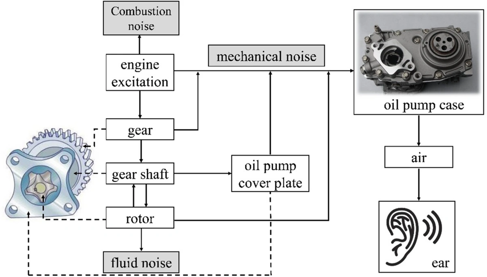
Image Source: Springer Link
Dimensional improvements in oil pump design are a vital frontier to improve engine efficiency. Modern engineering approaches target precise modifications to rotor components. These changes yield substantial performance benefits while you retain control of structural integrity.
Tooth Base Thickness Reduction from 5mm to 2.5mm
Oil pump rotor optimization starts with reducing tooth base thickness. Traditional designs use thicker tooth bases that exceed the work to be done, though they remain structurally sound. Engineers have found several performance advantages by reducing tooth base thickness from 5mm to 2.5mm without compromising reliability.
This change tackles a common industry problem. Traditional tooth profile designs based on trochoid or cycloid curves make rotors larger than needed. Industry experts point out that these designs “may be necessary to increase thickness (= sealing width) to meet the applicable pump specification requirements”. Parameter limits in conventional tooth profile design methods create this challenge.
The outer rotor component benefits from tooth base thickness reduction. This creates a more efficient profile that keeps volumetric efficiency high while reducing mechanical losses. Engineers must calculate precisely to maintain sealing performance against oil leaks as they remove material from non-critical areas.
Effect on Rotor Weight and Outer Diameter
Size and operational efficiency improve with optimized oil pump rotors. The outer diameter shrinks without affecting pump capacity. Manufacturer data shows optimized tooth profiles allow “rotor outer diameter -2[%]” reduction versus conventional designs.
The results are even better for operational friction. Tests show optimized rotor designs achieve “pump friction -7[%]” compared to standard production models. Cars benefit directly from this friction reduction through lower energy consumption and better engine efficiency.
Performance gains from dimensional optimization make more sense when you know that:
- Oil pumps cause about 10% of total engine energy loss
- Automatic transmissions see this number rise to 20-30%
- Hybrid vehicles lose 5-10% of total energy to oil pump operation
Engineers can shrink the physical footprint while keeping or improving pump performance through dimensional refinement. One manufacturer states that “applying original tooth profiles makes it possible to reduce size while maintaining pump capacity”.
b/a Ratio Optimization Between 20% to 40%
The b/a ratio defines specific dimensional proportions in rotor design and plays a key role in performance optimization. Research shows the best balance between flow efficiency and mechanical performance happens when this ratio stays between 20% to 40%.
This optimization solves tooth profile flexibility limits in conventional designs. Manufacturers can achieve compact dimensions and optimal performance by improving “tooth profile design flexibility by evolving the method used to design the trochoid-based rotor”.
Manufacturers develop their own tooth profile generation methods to work effectively. A leading company explains their approach: “The improved design flexibility is achieved by maneuvering the center position of a profile generating circle in a desired manner and adopting the curve described by a point on the profile generating circle as a tooth profile”.
These precise dimensional changes helped one manufacturer reduce diameter by 11% from conventional tooth profiles. They maintained high volumetric efficiency and reduced drive torque. Modern automotive design benefits from these improvements through better engine performance, lighter weight, and improved fuel economy.
Material Selection and Manufacturing Considerations
Material selection plays a vital role in manufacturing high-quality oil pump rotors. The right choice of materials and production methods will affect performance, durability, and reliability in demanding engine conditions.
Iron-Based Sintered Alloy in Rotor Fabrication
Iron-based sintered alloys are the foundations of most modern oil pump rotors. These materials offer excellent mechanical strength and precise dimensional control needed for smooth operation. Manufacturers use different alloy compositions for inner and outer rotors to get the best performance. The inner rotor uses FN-0208-30 alloy with a density of 6.70 g/cm³ and tensile strength of 310 MPa at 63 HRB hardness. The outer rotor uses FL-4205-45, which has a higher density (7.10 g/cm³) and better tensile strength (460 MPa).
These sintered alloys have copper (Cu) at 0.5-7% and carbon (C) at 0.1-0.98% with oxygen content between 0.02-0.3%. This formula creates the perfect balance of strength and dimensional stability. Some advanced formulas also use manganese (0.5-15%) to improve material properties.
Powder Metallurgy Techniques for Rotor Strength
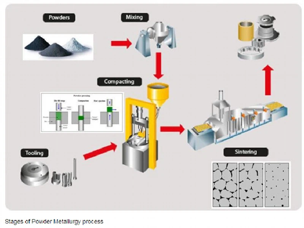
Powder metallurgy is the main way to make oil pump rotors. This method delivers exceptional precision and material properties that traditional machining cannot match. The process has four key stages:
- Powder Mixing: Manufacturers blend iron-based powders with binders like zinc stearate or lithium stearate to improve flow and compaction.
- Compaction: The powder mix goes through high-pressure compression (400-800 MPa) in engineered dies that shape the rotor.
- Sintering: The compressed parts heat up to about 1120°C in controlled environments. This causes solid-state diffusion that joins particles together. The process turns a fragile compact into a strong, dense component.
- Secondary Operations: The rotors then go through additional steps like sizing, machining, and surface treatments to meet final specifications.
Sintering fuses particles without melting them. This creates a unique structure that offers dimensional stability, low friction, and high wear resistance – key features for an efficient oil pump.
Durability and Static Breaking Load Matching
Oil pump rotor’s durability depends on its material properties and manufacturing quality. Powder metallurgy parts must resist mechanical stress, abrasion, and chemical exposure while fitting perfectly with other components. Surface treatments such as nitriding create harder surface layers that resist wear, corrosion, and fatigue better.
Mechanical strength is crucial for reliable operation. Tests show that powder metallurgy rotors keep their mechanical properties at high temperatures, unlike other materials that become weaker. The better strength-to-weight ratio from these manufacturing methods works well for applications that need both efficiency and performance.
Manufacturers carefully match static breaking load requirements to each application. This ensures rotors are strong enough for operational forces without extra weight that could reduce efficiency.
Performance Comparison with Conventional Designs

A comparison between conventional and improved rotor designs shows major performance differences in several operational parameters. The engineered modifications offer measurable advantages that affect engine efficiency and longevity.
Stress vs RPM Graph Analysis (Conventional vs Improved)
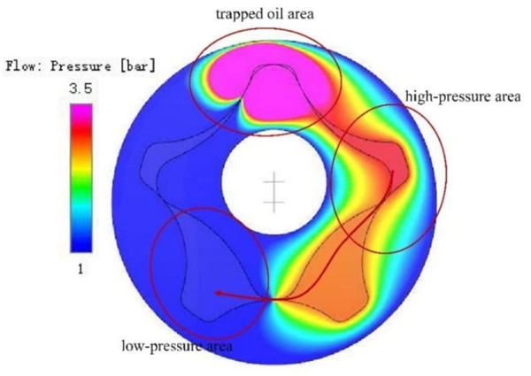
The operational stress patterns show clear differences between traditional and optimized rotor configurations. The rotor area shows both positive and negative pressure regions, and negative pressure drops below atmospheric levels. Traditional designs develop uneven stress concentrations across rotor surfaces as RPM increases. The improved designs, however, keep stress distribution more balanced even at high speeds.
Tests show that high rotational speeds magnify axial/radial clearances and meshing gaps in conventional pumps. The newer designs feature optimized tooth base geometry that alleviates this effect. This improvement lets operators extend operational parameters without risking component safety.
Power Consumption Reduction in New Design
Better rotor profiles lead to notable energy savings. The oil pump typically accounts for 10% of total energy loss in engines and 20-30% of loss in automatic transmission units. The improved designs tackle this inefficiency through several mechanisms:
Note that volumetric efficiency—the ratio of actual flow rate to theoretical flow rate—gets better with optimized tooth profiles. This improvement pairs with mechanical efficiency gains from reduced frictional resistance at sliding portions. The Geocloid rotor design shows a drive torque reduction of about 10% compared to conventional designs.
Tests confirm that variable-displacement pumps with optimized rotors can adjust oil pressure to 1-2 bars instead of the 4-6 bars from standard fixed-displacement pumps. This customization allows much lower flow rates and produces fuel economy improvements of 3-6% during both hot and cold starts.
Rotor Size and Weight Reduction Metrics
The dimensional improvements bring real benefits in size and weight. Some advanced designs reduce the outer diameter by 11% while keeping the same volumetric efficiency. A smaller rotor diameter leads to lower drive torque because of decreased frictional resistance losses.
Two-piece rotor designs help reduce weight even further. These were originally created for high-end applications where every gram counts. The optimized tooth profiles also cut pump friction by about 7% compared to standard production models.
Application in Engine Oil Pump Systems
Oil pump components need precise integration to maintain optimal lubrication throughout engine operation. These vital components are the foundations of engine protection systems in virtually all internal combustion applications.
Integration with Crankshaft Drive Mechanism
Most oil pumps connect directly to the engine’s power source through mechanical geartrains linked to the crankshaft. Direct connection will give a reliable operation without complex intermediary components. Many designs employ the camshaft (if mounted in the cylinder block) or distributor shaft that turns at half engine speed. This reduced speed ratio helps pump longevity while maintaining adequate flow.
Several configuration options exist:
- Direct mounting on crankshaft nose with internal gears
- Vertical drive shafts using helical skew gears from camshaft
- Timing belt/chain drives from crankshaft
Oil Inlet and Outlet Chamber Configuration
A wire mesh strainer removes larger debris particles as the pump draws oil from the sump. The pickup pipe’s protective screen prevents major contaminants from entering the system. Some designs feature bypass valves that allow continued—albeit unfiltered—oil flow if completely blocked, which prioritizes engine survival over potential pump damage.
Pressure builds up between inlet and outlet chambers through restriction rather than pump action. Experts note that “oil pressure is not produced by the oil pump. The oil pressure is caused by restrictions to the flow of oil – through narrow passageways, jet nozzles, and tight bearing clearances”.
Use in Internal Combustion Engine Lubrication
Oil pump operation serves multiple critical functions beyond simple lubrication in the engine. The circulating oil removes heat effectively from pistons, bearings, and shafts. This continuous flow sends oil to different engine components, including pistons, rings, springs, and valve stems.
Engine failure occurs faster—typically within minutes—without adequate circulation. Oil pumps must maintain consistent pressure between 1-6 bars based on engine design and operational state.
Conclusion
Recent state-of-the-art developments in oil pump rotor design have shown remarkable potential to solve performance problems in modern engines. Several major improvements in rotor design have emerged as influential breakthroughs. A reduction in tooth base thickness from 5mm to 2.5mm delivers clear benefits to mechanical performance and dimensional efficiency while maintaining structural integrity.
Better tooth profiles help create smaller, lighter pumps that maintain or improve volumetric efficiency. These upgrades lead to 7% lower friction losses and less power consumption. Oil pumps make up about 10% of total engine energy loss, so these efficiency improvements mark real progress toward better vehicle fuel economy.
Powder metallurgy techniques are the foundations of these performance improvements. Sintered components’ precision-controlled microstructure and exceptional dimensional stability create the perfect base for high-performance oil pump rotors. JH MIM, a 20-year old company with deep powder metallurgy expertise, plays a vital role in manufacturing these precision-engineered components for automotive clients worldwide.
Better stress distribution through optimized tooth base geometry helps rotors stay structurally sound at high speeds. Engineers can now design compact, lighter pumps that remain durable and reliable. These size optimizations also reduce noise and vibration – qualities that matter more than ever in modern vehicle design.
Car manufacturers keep pushing for greater efficiency and lower emissions. Optimized oil pump rotor design shows how precision engineering can transform even traditional components. The rise from standard to improved designs proves that small changes in tooth geometry and manufacturing methods can deliver impressive performance gains in multiple areas. These advances ensure proper engine lubrication with less energy use and help create more efficient, environmentally friendly transportation systems.
Key Takeaways
Oil pump rotor design optimization offers significant opportunities to improve engine efficiency and performance through strategic dimensional modifications and advanced manufacturing techniques.
• Reduce tooth base thickness by 50% – Cutting thickness from 5mm to 2.5mm decreases pump size by 11% while maintaining volumetric efficiency and reducing drive torque by 10%.
• Achieve 7% friction reduction – Optimized tooth profiles and powder metallurgy manufacturing enable measurable friction losses reduction compared to conventional designs.
• Target 10% energy savings potential – Since oil pumps account for 10% of total engine energy loss, improved rotor designs directly contribute to fuel economy gains.
• Optimize b/a ratio between 20-40% – This dimensional proportion creates the ideal balance between flow efficiency and mechanical performance in rotor operation.
• Use iron-based sintered alloys – Powder metallurgy techniques provide superior dimensional control, strength-to-weight ratios, and wear resistance compared to traditional machining methods.
These engineering improvements address a critical inefficiency in automotive systems while maintaining the structural integrity and reliability essential for engine protection. The combination of dimensional optimization and advanced manufacturing techniques demonstrates how precision engineering can transform established components for better performance.
FAQs
Q1. How does an oil pump impact engine performance? An oil pump plays a crucial role in engine performance by circulating oil throughout the system. If it malfunctions, you may experience lower oil pressure, which can lead to decreased engine performance and potentially even complete engine failure if left unaddressed.
Q2. What type of oil pump design is most efficient for high-volume oil circulation? High-volume oil pumps are the most efficient for moving large quantities of oil. These pumps feature larger gears that can move more oil per revolution, making them ideal for performance engines with larger bearing clearances.
Q3. What are some common oil pressure issues in engines? Common oil pressure problems include low oil levels, faulty oil pressure sensors, worn engine bearings, and failing oil pumps. These issues can range from simple fixes to more serious engine problems requiring extensive repairs.
Q4. How do optimized oil pump rotors improve engine efficiency? Optimized oil pump rotors, with reduced tooth base thickness and improved tooth profiles, can decrease pump size by up to 11% while maintaining volumetric efficiency. This design can reduce drive torque by 10% and friction losses by 7%, contributing to overall engine efficiency and fuel economy.
Q5. What materials are best suited for manufacturing oil pump rotors? Iron-based sintered alloys manufactured through powder metallurgy techniques are ideal for oil pump rotors. These materials provide superior dimensional control, excellent strength-to-weight ratios, and high wear resistance, which are crucial for the efficient and reliable operation of oil pumps in engine systems.