Oil pump gears act as the beating heart of engine lubrication systems and determine how well oil moves through an engine. These precision-engineered components keep oil pressure at the right levels—usually 10 psi per 1000 revolutions per minute, with peaks at 55-65 psi. Poor circulation can trap air in the oil and then cause engine damage.
The oil pump’s operation depends on rotating gears that alter the working chamber’s volume through their meshing action. Engine systems can employ different gear configurations, and external oil pump gears usually run at slower speeds around 600 rpm. Manufacturers must create both the oil pump drive gear and driven gear with extreme precision because their shape and meshing accuracy affect how well they work and last. Oil pump gears that have more teeth create smoother flow with less leakage. Internal meshing gear pumps pack several benefits into their design – they’re compact, small, and lightweight. These pumps handle fluids of all types, from thick petroleum to thinner lubricating oils. This piece examines these key components, including ones made through the powder metallurgy process.
Working Principle of Oil Pump Gears in Engine Systems
The oil pump gear system works through a precise mechanical process that keeps oil flowing reliably throughout the engine. These positive displacement pumps differ from other designs because they move fluid by trapping fixed amounts and pushing them into discharge pipes.
Gear Meshing and Oil Entrainment Process
Two meshed gears form the heart of an oil pump’s operation. These gears rotate within a sealed chamber, and their teeth separate on the suction side to create a void with low pressure. The pressure difference pulls oil from the sump into spaces between the gear teeth and pump housing. The oil gets trapped and moves along the outer walls of the pumping chamber as the gears turn. The gears maintain tight clearances with the pump casing to prevent backflow and are often made through powder metallurgy to last longer.
Suction and Discharge Cycle in Positive Displacement
The expanding volume inside the pumping chamber pulls fluid through the inlet port during the suction phase. Sealing elements block any backflow once the oil fills the chamber. The gears then come together on the discharge side, which reduces the spaces between teeth and forces the trapped oil out through the discharge port at higher pressure. This cycle creates a flow rate that directly matches pump speed, which lets positive displacement pumps control flow precisely.
Role of Oil Pump Drive Gear in Rotation Synchronization
The oil pump drive gear connects to the engine’s power source and makes the idler gear move in the opposite direction, creating the pumping pattern that moves fluid. Mechanical geartrains linked to the crankshaft typically drive these gears to keep things simple and reliable. Most designs cut pump speed in half by connecting it to the camshaft or distributor shaft. A near-vertical drive shaft with helical skew gears helps achieve optimal performance in this setup.
Component alignment plays a crucial role, and many systems use marking dots or arrows that help ensure proper synchronization during assembly. This careful arrangement helps the oil pump deliver steady pressure across all engine operating conditions.
Types of Oil Pump Gears and Their Functional Differences
Engine oil systems use two main types of pump gear configurations that have unique operational characteristics for specific applications.
External Gear Set: Drive and Idler Gear Configuration
External gear sets use two similar gears that rotate in opposite directions inside a precision-machined housing. The driving gear connects directly to the power source, and the second gear works as the idler gear. The rotating gears create expanding volume at the inlet side and draw fluid into spaces between the teeth and housing. The fluid moves along the perimeter—around the gears rather than between them—until the teeth remesh and force it out on the discharge side.
External gear pumps run at speeds between 640-3450 rpm based on their size, and smaller pumps operate at higher speeds. These pumps can handle pressures that exceed 3000 PSI because they have four bearings that support the liquid and shaft on both sides of the gears. This resilient infrastructure makes them perfect for precise transfer jobs with fuels and hydraulic systems. The external configurations can use spur, helical, or herringbone gears, and the last two options provide smoother flow.
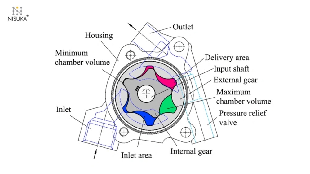
Internal Gear Set (Gerotor): Eccentric Motion and Flow Control
Internal gear sets, also known as gerotors, work differently. They use an inner rotor with n teeth that mesh with an outer rotor’s n+1 teeth. The inner rotor sits off-center inside the outer rotor and creates eccentric motion as it turns. This setup forms chambers that expand and contract to pull in fluid on one side while pushing it out on the other.
The gerotor’s performance depends on precise tooth profiles and controlled clearances against side plates and housing. These pumps deliver smoother flow than external gear designs when built with tight tolerances—often using powder metallurgy processes. They work great in automotive applications because they’re compact and quiet.
Bi-directional Operation in Internal Gear Pumps
Internal gear pumps stand out because they can run in both directions. You can switch them from one rotation direction to another, or set them up to work well in both directions. This flexibility lets a single pump do many jobs, like loading and unloading vessels through the same line.
You need to check several things before reversing an internal gear pump: valve orientation, seal circulation plans, and internal lubrication paths. Internal relief valves protect against overpressure in just one direction, so they need repositioning when reversing flow. Some models also have lubrication holes that send pressurized fluid to bushings—these paths might need changes to work well in reverse.
Material Selection and Powder Metallurgy in Gear Manufacturing
Material selection is a vital factor that determines how well oil pump gears perform and last in engines of all types. Each application needs specific materials that work best for optimal results.
Steel and Heat-Treated Alloy Applications
Steel stands out as the top choice for oil pump gears that need high strength and exceptional wear resistance. Heat-treated alloy steels provide long service life when used under high-pressure and speed conditions. High-performance applications benefit from steel alloys with nickel that deliver excellent strength-to-weight ratios. Adding chromium boosts wear resistance and hardenability.
Cast Iron for Low-Cost, Moderate Load Use
Cast iron gives you good machinability, thermal stability, and vibration-damping characteristics for oil pump gears. The dense, granular microstructure of cast iron naturally absorbs vibration and runs more quietly. This affordable material works well for moderate load applications. Modern automotive oil pumps use cast iron less often than other materials.
Powder Metallurgy Process: Press-and-Sinter Route
The powder metallurgy (PM) process uses a controlled press-and-sinter route that starts with carefully picked metal powders. Iron-based powders—often mixed with copper or nickel—blend with lubricants to flow and compact better. High-pressure compaction in precision dies creates a “green gear” with accurate tooth geometry. The process ends when these compacts bond through solid-state diffusion in a continuous furnace under a protective atmosphere.
Surface Densification and Case Hardening Techniques
Surface densification techniques make powder metallurgy gears much stronger. You get better surface density while keeping the cost benefits of single pressing and sintering. Radial rolling pushes the surface density close to full density, which substantially improves rolling contact fatigue behavior—making it similar to wrought steels. Case hardening adds more strength through carburizing that creates a hardened layer. This improves load capacity while keeping a tough, ductile core.
Oil Impregnation for Self-Lubricating Gears
Powder metallurgy materials have controlled porosity that creates unique self-lubricating properties. These pores hold oil inside the gear structure. The oil-filled spaces work like tiny reservoirs that keep contact surfaces lubricated, which cuts down friction and wear. Tests show self-lubricating gears have friction coefficients just like externally lubricated ones. This means longer service life and less maintenance.
Performance and Application of Engine Oil Pump Gears

Oil pump gears play vital roles in many industries. Each industry needs these gears to meet specific performance requirements and handle unique operational challenges.
Oil Pump Gears in Automotive and Diesel Engines
Engine oil pumps keep pressure at about 10 psi per 1000 rpm. The pressure peaks between 55-65 psi. Powder metallurgy gears work great in cars. Their controlled porosity lets oil soak in, which makes them self-lubricating. The oil pump’s biggest job is getting oil to the connecting rod bearing that sits farthest from the pump. The oil must travel three to four feet through tiny passages. A 350 Chevy engine running at 6500 rpm pushes oil at its outer edge at 107.9 mph. This shows just how tough these parts need to be.
Hydraulic System Integration in Mobile Machinery
Hydraulic pumps in mobile machinery turn mechanical energy into hydraulic energy before sending it back into the system. These machines often use open loop gear pumps that give non-stop fluid power. Both actuator-return and inlet ports link to the hydraulic reservoir. This setup helps systems run cooler because the reservoir helps get rid of heat. Open loop systems might be more complex than closed ones, but they let designers be more flexible – perfect for different mobile equipment needs.
Industrial Lubrication and Thermal Management
Pressurized oil now does more than just lubricate – it works as a hydraulic fluid to power small actuators. Gear pumps help manage heat in industrial settings by keeping oil moving steadily. Gears churning creates heat – like in water wheels – and this adds to the heat from friction between gears. Even the most efficient helical gears (99%) lose about 1% of power, mostly as heat.
Impact of Gear Tooth Geometry on Flow Consistency
The shape of gear teeth makes a big difference in how smoothly oil flows. Dislocation gear pumps flow by a lot smoother than straight ones. The flow gets better by 27% at 1100 rpm and 35% at 2700 rpm. Helical, herringbone, and staggered gear oil pumps also make oil flow smoother thanks to their special shapes. This smooth flow really matters for jobs that need precise, steady oil delivery.
High RPM Performance in Racing Engines
Racing engines can hit 8500-9000 rpm, so they need special gear pumps that stay reliable and efficient [20]. Racing oil pumps must:
- Keep the oil pressure steady, no matter the RPM
- Work well under stress and high heat
- Cut down engine drag while giving the best lubrication
The Robinson High Volume Oil Pump Gear runs about 8% faster. This means more oil flows at high RPMs without causing cavitation. This matters because cavitation creates tiny shockwaves when bubbles pop, which can eat away at metal where fluid moves fast.
Conclusion
Oil pump gears are the heart of engine lubrication systems that determine engine life and performance. This piece explores how these precision-engineered parts maintain proper oil pressure—typically 10 psi per 1000 rpm—and ensure consistent circulation through complex engine systems.
External and internal gear configurations each bring unique benefits to different applications. External gear sets work well under high pressure conditions. Internal gerotor designs create smoother flow with minimal pulsation. The gear tooth’s geometry affects performance, and helical and herringbone patterns substantially reduce flow pulsation compared to straight-tooth designs.
Material choice makes all the difference in oil pump gear durability. Steel and heat-treated alloys shine in high-performance uses, while cast iron provides budget-friendly options for moderate loads. Powder metallurgy has brought groundbreaking changes to oil pump gear manufacturing through its press-and-sinter route. This process creates parts with controlled porosity that allows oil impregnation to improve self-lubrication properties while keeping tight dimensional tolerances.
Surface densification and case hardening applied to powder metallurgy gears boost their load-bearing capacity. These treatments create components matching wrought steel performance while keeping the sintering process’s economic benefits. The resulting self-lubricating gears show lower friction coefficients and longer service life in a variety of applications.
Automotive engineers must pick oil pump gear specifications based on operating conditions. Standard engines work fine with conventional designs. Racing applications just need specialized configurations that maintain proper oil pressure at 8500-9000 rpm without cavitation or excessive engine drag.
Powder metallurgy gears are the future of engine efficiency and reliability. Their unique mix of precise dimensional control, self-lubricating properties, and excellent wear resistance makes them perfect for meeting tough performance requirements in automotive, industrial, and specialized applications.
Key Takeaways
Understanding oil pump gears is crucial for engine performance, as these components maintain critical oil pressure and circulation that prevents catastrophic engine damage.
• Oil pump gears maintain 10 psi per 1000 rpm pressure, using positive displacement to trap and force oil through engine systems continuously.
• External gear sets handle high pressure (3000+ PSI) applications, while internal gerotor designs provide smoother flow with 27-35% less pulsation.
• Powder metallurgy manufacturing creates self-lubricating gears through controlled porosity and oil impregnation, extending service life significantly.
• Material selection impacts performance: steel alloys for high-stress applications, cast iron for cost-effectiveness, with surface treatments enhancing durability.
• Racing engines require specialized gear pumps operating at 8500-9000 rpm, with helical tooth geometry reducing flow pulsation for consistent lubrication.
Proper oil pump gear selection and maintenance directly correlates with engine longevity, making these components essential for both standard automotive and high-performance applications.
FAQs
Q1. How do oil pump gears function in an engine? Oil pump gears work as a positive displacement pump. They create suction to draw oil in, then use meshing gears to trap and force the oil through the engine’s lubrication system. As the gears rotate, they create expanding and contracting chambers that pull in oil on one side and push it out on the other, maintaining consistent oil pressure and circulation.
Q2. Can an oil pump impact engine performance? Yes, an oil pump significantly affects engine performance. A properly functioning oil pump ensures adequate oil pressure and circulation, which is crucial for engine lubrication and cooling. If the oil pump malfunctions, it can lead to decreased engine performance, increased wear on components, and potentially even complete engine failure if left unaddressed.
Q3. What are the main types of oil pump gears used in engines? There are two primary types of oil pump gears: external gear sets and internal gear sets (gerotors). External gear sets use two identical gears rotating in opposite directions, while internal gear sets have an inner rotor with fewer teeth than the outer rotor, creating an eccentric motion. Each type has its advantages in terms of pressure handling, flow consistency, and application suitability.
Q4. How do gear pumps perform in various applications? Gear pumps are known for their reliability, simplicity, and strength. They perform well under high pressure and in tough conditions, delivering a steady flow of fluid. They are particularly effective at handling high-viscosity fluids, making them suitable for a wide range of applications from automotive engines to industrial machinery.
Q5. What materials are commonly used in manufacturing oil pump gears? Oil pump gears are typically made from materials such as steel, heat-treated alloys, and cast iron. Steel and heat-treated alloys are preferred for high-performance applications due to their strength and wear resistance. Cast iron is used for more cost-effective, moderate load applications. Additionally, powder metallurgy techniques are increasingly used to create gears with unique properties like self-lubrication and enhanced durability.