
Key Takeaways
Selecting the optimal powder metallurgy route for precision gears determines whether a power transmission assembly achieves target load capacity, tooth accuracy, and fatigue life while staying within production budget constraints.
- Geometry Constraints: Choose Metal Injection Molding (MIM) for complex 3D pinions with transverse cross-holes, undercuts, multi-tier stepped gears, or non-straight draw profiles. Use Pressed & Sintered PM for high-volume 2D spur and helical gears with a straight compaction axis.
- Density & Strength Differences: MIM achieves >96% to 99% of theoretical density (yielding near-wrought dynamic fatigue resistance and tensile strength >1600 MPa after heat treatment). Standard pressed PM achieves 85% to 92% density, requiring secondary copper infiltration or gear rolling for extreme torque loads.
- Sintering Shrinkage: MIM feedstocks undergo 15% to 20% isotropic shrinkage during debinding and sintering due to fine powder (<20 μm) and high binder loading. Pressed PM uses coarse powder (50 to 100 μm) and undergoes under 1% dimensional shrinkage.
- Economics & Tooling Amortization: Pressed PM tooling is lower cost ($5,000 to $20,000) with low commodity raw material costs, ideal for volumes of 10,000+ units. MIM tooling ($15,000 to $50,000+) requires annual volumes typically exceeding 50,000 units to offset fine powder premiums through the total elimination of secondary multi-axis CNC machining.
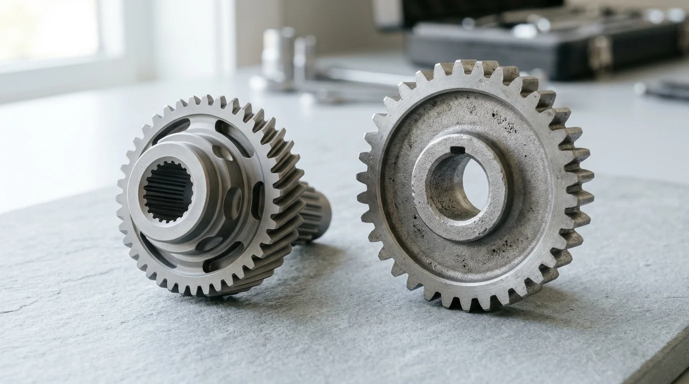
Small pinions can create big manufacturing trade-offs. A gear that looks simple in CAD may demand tight tooth accuracy, high fatigue strength, cross-holes, hubs, grooves, or compact 3D features that push conventional powder metallurgy to its limits.
Metal Injection Molding (MIM) and conventional pressed sintered PM both start with metal powder and end with sintered parts, but they differ sharply in powder size, compaction method, shrinkage, achievable density, and design freedom. For engineers sourcing precision gear components, the right choice affects not only unit cost, but also tool feasibility, secondary machining, durability, and production scalability. This comparison explains where each process performs best and how to match the route to the pinion’s geometry and load requirements.
MIM vs. Pressed Sintered Gears: Core Differences
Powder metallurgy (PM) has long been established as a highly efficient manufacturing method for producing complex, high-volume mechanical components. When engineering complex pinions and gear trains, manufacturers typically evaluate two primary branches of PM: Metal Injection Molding (MIM) and conventional press and sinter powder metallurgy. While both rely on the consolidation and sintering of metal powders, their underlying physics, material properties, and geometric capabilities diverge significantly.
How Metal Injection Molding Works
Metal Injection Molding combines the geometric versatility of plastic injection molding with the mechanical integrity of solid metal. The process begins with a feedstock composed of extremely fine metallic powders—typically ranging from 10 to 20 microns in diameter—blended with a thermoplastic and wax binder system. This feedstock is heated and injected under pressure into a highly complex, multi-part mold cavity to form an oversized “green” part.
Once molded, the component undergoes a debinding phase, using catalytic, thermal, or solvent methods to extract the primary binder, leaving a porous “brown” part. The final step is high-temperature sintering in a controlled atmosphere. Because the starting powders are exceptionally fine and the binder volume is large, the part undergoes significant, isotropic shrinkage—often between 15% and 20%—as it densifies to a near-solid state, with final densities typically exceeding 96% of the theoretical maximum.
How Pressed and Sintered Powder Metallurgy Works
Conventional press and sinter powder metallurgy operates on a fundamentally different mechanical principle. The process utilizes coarser metal powders, generally between 50 and 100 microns, which are blended with a small amount of solid lubricant (usually less than 1% by weight) rather than a heavy thermoplastic binder. This powder mixture is gravity-fed into a rigid tool steel or tungsten carbide die.
Compaction is achieved through uniaxial pressure applied by upper and lower punches, typically requiring massive compaction forces ranging from 400 to 800 MPa. The resulting green part relies on the mechanical interlocking of the coarse powder particles to maintain its shape. During the subsequent sintering process, the part undergoes minimal shrinkage (usually under 1%). However, because the compaction is uniaxial and lacks the fluid dynamics of injection molding, the final sintered density is generally lower, typically falling between 85% and 92% unless secondary operations like double-press-double-sinter (DPDS) or copper infiltration are employed.
Key Differences in Shape Capability and Density
| Process Characteristic | Metal Injection Molding (MIM) | Pressed & Sintered PM |
|---|---|---|
| Typical Powder Size | 10 – 20 μm | 50 – 100 μm |
| Compaction Method | Hydrostatic Injection | Uniaxial Pressing |
| Sintering Shrinkage | 15% – 20% (Isotropic) | < 1.0% |
| Typical Final Density | > 96% to 99% | 85% – 92% |
| 3D Feature Capability | Excellent (Undercuts, cross-holes allowed) | Limited (Straight draw axis required) |
Design Factors That Drive Process Selection
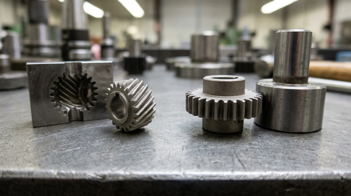
Translating a pinion design from a CAD model to a manufacturable component requires a rigorous assessment of geometric and dimensional constraints. The selection between MIM and pressed and sintered PM is rarely arbitrary; it is heavily governed by the gear’s physical architecture, mass, and the precision required for seamless engagement in the final assembly.
Gear Geometry and Feature Complexity
Gear geometry is the most immediate filter for process selection. Helical gears with high helix angles, pinions with integrated asymmetric hubs, or shafts requiring transverse cross-holes naturally favor Metal Injection Molding. Because MIM utilizes multi-slide tooling and collapsible cores, it can form complex geometries that bypass the need for subsequent CNC machining. If a pinion design features an undercut or a flange on both ends of a central gear, uniaxial pressing simply cannot eject the part from the die.
Conversely, if the pinion features a straightforward spur gear profile or a stepped design that consistently tapers in one direction, pressed and sintered PM becomes highly attractive. Pressing excels at generating precise, repetitive 2D profiles. For complex pinions that require a central bore with internal splines or keyways, both processes can accommodate the internal geometry, provided there is no draft angle conflict in the press direction.
Part Size, Weight, and Aspect Ratio
Part mass and aspect ratio dictate the physical limits of both processes. MIM is economically and technically optimized for small, lightweight components. The ideal weight range for a MIM pinion falls between 0.1 and 100 grams, with an absolute upper limit generally capped around 250 grams. Beyond this mass, the cost of fine metal powders and extended debinding times render the process commercially unviable. MIM also excels at thin-walled structures, capable of forming sections down to 0.5 mm.
Press and sinter PM, on the other hand, is highly scalable in terms of mass, routinely producing gears weighing anywhere from 50 grams up to several kilograms. However, press compaction struggles with extreme aspect ratios. Because compaction force dissipates through the powder column due to die-wall friction, length-to-diameter (L/D) ratios exceeding 3:1 often result in severe density gradients. A long pinion shaft produced via pressing may have a dense top and bottom but a porous, mechanically weak center.
Tolerance, Surface Finish, and Strength Requirements
Dimensional accuracy and surface finish are critical for gear meshing and acoustic performance. MIM typically achieves as-sintered tolerances of ±0.3% to ±0.5% of nominal dimensions, translating roughly to IT8 to IT10 ISO tolerance grades. The as-sintered surface finish is generally excellent (Ra 0.8 to 1.5 μm), which often eliminates secondary polishing. Furthermore, near-wrought density (e.g., MIM-4605 or MIM-4140 steel) allows heat treatments that push ultimate tensile strength (UTS) beyond 1600 MPa.
Pressed and sintered gears typically hold tighter dimensional tolerances in the radial (die-bound) direction, often achieving IT7 to IT9 grades, especially when secondary coining or sizing operations are used. However, axial tolerances (direction of pressing) are inherently wider. The surface finish of pressed PM is rougher due to coarser powder and surface porosity. To achieve high strength, pressed gears require higher carbon content, copper infiltration, or surface densification techniques like gear rolling to close surface pores and enhance rolling contact fatigue performance.
Evaluating a Complex Gear or Pinion Design?
Don’t let secondary CNC machining inflate your unit cost. JHMIM provides custom DFM engineering reviews to help you choose between MIM and pressed powder metallurgy for maximum performance and minimum total component cost.
Send Us Your Gear 3D CAD Drawing for a Free DFM Review & Quote Within 24 Hours →
Cost, Volume, and Manufacturing Trade-Offs
While technical specifications dictate what is possible, commercial viability determines what is actually produced. The financial architecture of MIM and pressed and sintered PM differs significantly regarding upfront capital expenditure, variable unit costs, and production volumes required to achieve acceptable ROI.
Tooling Cost and Unit Cost
Tooling costs represent a substantial barrier to entry for both processes, but the investment scales differently. MIM requires complex, multi-cavity injection molds capable of handling abrasive feedstocks. Depending on complexity and cavity count (often 4, 8, or 16 for high-volume pinions), a MIM tool costs between $15,000 and $50,000+. In contrast, press and sinter tooling utilizes rigid tungsten carbide or high-alloy steel dies and punches, typically ranging from $5,000 to $20,000.
Unit costs invert this relationship. The raw material for MIM—highly refined spherical powders mixed with thermoplastic binders—is more expensive, carrying a 5x to 10x cost multiplier over standard PM powders. Consequently, while a pressed gear might have a raw material cost measured in cents, an equivalent MIM part carries a higher material baseline, which must be offset by eliminating secondary machining operations.
| Cost Driver | Metal Injection Molding (MIM) | Pressed & Sintered PM |
|---|---|---|
| Typical Tooling Cost | $15,000 – $50,000+ | $5,000 – $20,000 |
| Raw Material Cost | High (5x – 10x fine powder premium) | Low (Commodity PM powder) |
| Secondary Machining | Rarely required (Net-shape 3D capabilities) | Often required for 3D cross-features |
| Energy Consumption | High (Extended debinding & sintering) | Moderate (Rapid compaction & sintering) |
Annual Volume and Production Scalability
Tooling cost amortization necessitates volume thresholds. For MIM to be economically advantageous, annual volumes typically need to exceed 50,000 units, where automated multi-cavity injection molding drives down per-part labor costs. Pressed and sintered PM is efficient at massive scales (millions of units for automotive gears), but because tooling is less expensive, standard PM is also viable at lower volumes (10,000 to 20,000 units per year). Rapid compaction cycle times (10 to 30 parts per minute) ensure virtually unlimited production scalability.
How to Choose the Right PM Gear Process
Selecting the optimal powder metallurgy process for a complex pinion requires a systematic evaluation of design intent, environmental operating conditions, and supply chain constraints. By aligning the gear’s critical-to-quality (CTQ) attributes with process strengths, engineers establish a scalable manufacturing pipeline.
Process Selection Checklist
- Geometric Assessment: If the pinion possesses transverse holes, undercuts, non-straight draw splines, or orthogonal threads, select MIM to avoid multi-axis secondary CNC machining.
- Weight & Mass Limits: If the part weighs over 150 to 250 grams, specify Pressed & Sintered PM to prevent prohibitive raw material costs.
- Load & Fatigue Requirements: For high-torque, high-impact drive mechanisms (power tool gearboxes, automotive actuators), choose MIM for near-100% density and superior tooth bending fatigue. For kinematic transfer gears under moderate loads, specify pressed PM for maximum cost efficiency.
Prototype and Supplier Validation Protocols
Before committing tens of thousands of dollars to production tooling, rigorous prototype and quality validation must be completed:
- Prototype Machining & Soft Tooling: Utilize CNC-machined wrought stock or single-cavity prototype MIM molds to validate gear ratio, meshing noise, and tooth contact patterns in real assembly test rigs.
- Double-Flank Gear Roll Testing: Evaluate total composite error (TCE) and tooth-to-tooth composite error (TTE) to verify AGMA or DIN accuracy classes on sample production batches.
- Metallurgical & Density Verification: Conduct destructive microstructural analysis to verify core density (>96% for MIM), grain size, and case-hardening depth after heat treatment.
Frequently Asked Questions
When should a complex pinion be made with MIM instead of press and sinter PM?
Choose MIM when the pinion requires 3D features such as transverse cross-holes, undercuts, multi-tier stepped gears, or high density above 96% theoretical. MIM is ideal when secondary CNC machining would erase the cost advantage of conventional PM.
When is conventional pressed and sintered PM the better gear process?
Pressed and sintered PM is superior for high-volume spur or helical gears with straight 2D geometry aligned with the pressing axis. It provides maximum cost efficiency when mass exceeds 150 grams and moderate density (85% to 92%) satisfies mechanical load requirements.
How do MIM and pressed sintered gear densities compare?
MIM parts achieve >96% to 99% of theoretical density after high-temperature vacuum sintering. Conventional pressed PM gears typically achieve 85% to 92% density unless secondary operations like double-press-double-sinter (DPDS) or copper infiltration are specified.
Why does MIM allow more complex gear geometry?
MIM blends fine metal powder with a thermoplastic binder and injects the fluid feedstock into a mold cavity. This hydrostatic flow allows complex 3D details, internal threads, and undercuts that rigid uniaxial compaction punches cannot eject.
Does MIM shrink more than press and sinter PM?
Yes. MIM parts undergo 15% to 20% isotropic shrinkage during debinding and sintering because of fine powder size (<20 μm) and high binder loading. Pressed PM uses coarser powders (50 to 100 μm) and exhibits less than 1% sintering shrinkage.