Metallurgical Testing for MIM Parts
MIM metal components reach an exceptional 96-99% density, which is nowhere near what other metal forming processes can achieve. Metal Injection Molding’s remarkable density makes it the lifeblood of manufacturing complex, high-performance metal parts that serve industries of all types.
This innovative process blends the flexibility of plastic injection molding with traditional metallurgy’s strength and durability. Parts produced through MIM feature complex geometries and precise tolerances of ±0.3% after sintering. Raw materials convert into usable parts at an impressive rate of 98%. The process involves a controlled 15-20% shrinkage during the sintering phase, when metal particles bond together to form the final component.
MIM’s value stems from its precision, efficiency, and adaptability with different metals. Manufacturers create components using stainless steel, titanium, and other high-performance alloys. These components end up in medical devices, automotive systems, electronics, and firearms. The applications range from surgical instruments and orthodontic brackets to turbocharger components and fuel system parts. This piece examines the most important metallurgical testing methods that help MIM components meet strict standards for these challenging applications.
Key Metallurgical Factors Influencing MIM Part Quality
Metal injection molded parts’ quality depends substantially on three interconnected metallurgical factors that need precise control throughout manufacturing.
Feedstock Homogeneity and Powder Size Distribution
MIM manufacturing’s success starts with proper feedstock preparation. Fine metal powders between 4 to 25 microns combine with a thermoplastic binder system. The powder’s size distribution affects flowability, packing density and the part’s final performance. Spherical powders flow better because they have less inter-particle friction. Irregular particles give better green strength through mechanical interlocking, but can create non-uniform packing and more porosity. The distribution slope parameter (Sw) shows how well a feedstock molds. Powders with Sw values near 2 (broad distributions) mold easier, while those above 7 (narrow distributions) are harder to work with.
Binder Composition and Mixing Ratios
The binder system has a backbone polymer, waxes that improve flow, and surfactants that help powder dispersion. Metal powder and binder proportions range from 40-68% and 60-32% by volume. The critical solid loading (CSL) represents the best powder-to-binder ratio where particles pack tightly with binder filling all voids. Finding this balance needs careful testing. Too much binder leads to slumping during debinding, while extra powder creates trapped air pockets and makes the mixture too viscous. Batch-to-batch consistency in feedstock must be perfect, as any changes can cause molding defects and distort sintering.
Sintering Temperature Profiles and Shrinkage Control
Sintering temperature profiles shape the part’s final properties. HK30 stainless steel sintered at 1280°C for 7 hours reaches optimal density (7.61 g/cm³), micro-hardness (187 HV1.0), and tensile strength (570 MPa). Temperatures at 1300°C can overheat and weaken grain boundary bonds. MIM parts shrink 15-20% during sintering. Shrinkage rates change based on material composition, part geometry, and processing parameters. Materials like 316L stainless steel need molds designed with 16.5% compensation factors. Even temperature distribution and controlled cooling throughout sintering help reduce warping and size variations.
Dimensional and Surface Integrity Testing Methods
Quality control in MIM parts needs systematic testing methods to check both external looks and internal structure. The quality control’s success depends on choosing the right inspection techniques for each quality parameter.
Visual Inspection for Surface Defects in Green and Sintered Parts
Visual inspection serves as the basic quality control method in MIM manufacturing. Operators look at components under controlled lighting to spot surface defects like cracks, voids, burrs, and discolorations [11]. This technique quickly shows visible flaws before parts move to advanced testing stages. The results vary based on the operator’s experience, which makes it hard to maintain consistent standards [12].
Coordinate Measuring Machines (CMM) for Post-Sintering Accuracy
CMMs check critical dimensions with micrometer-level precision using touch-probe technology that moves along three Cartesian axes (X, Y, Z). These systems are great at checking complex MIM geometries after sintering. CMMs’ accuracy usually depends on room temperature, and manufacturers specify their performance using continuous thermal specifications across temperature ranges. Temperature correction plays a vital role in shop floor inspections since thermal changes can affect the results.
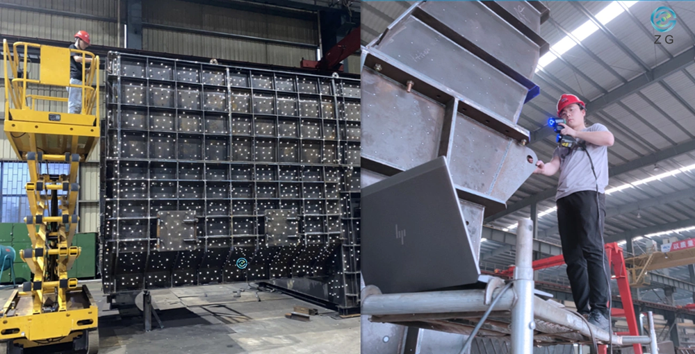
3D Scanning for Complex Geometries
3D scanning captures thousands of data points quickly for MIM parts with complex organic shapes that regular measuring tools can’t check properly. Modern scanners use structured blue light and high-resolution cameras to create full-field 3D coordinates in seconds. This technology works well with reflective surfaces and indentations, giving complete data for parts with intricate features.
CT Scanning for Internal Defect Mapping
Industrial CT scanning shows both external and internal structures of MIM components without damaging them. This method spots porosity, voids, and micro-cracks that might happen during injection and sintering. CT scanning helps visualize metal particle distribution in the mold and optimize process settings like molding pressure, injection speed, and sintering temperature. The CT data also helps validate early prototypes, which reduces defect risks in mass production.
Mechanical Testing for Performance Validation
MIM part qualification depends heavily on mechanical performance validation. This process reveals ground behavior characteristics that visual inspection misses. Tests give us clear data about part performance under actual operating conditions.
Tensile Testing According to ASTM E8 Standards
Tensile testing measures key mechanical properties based on ASTM E8 standards. The process applies increasing tensile force until the specimen fails. This creates stress-strain curves that show ultimate tensile strength, yield strength, and elongation. The test needs specimens with specific geometries. These are usually dogbone-shaped rectangles with a 50mm gage length. MIM titanium alloys such as Ti-6Al-4V show remarkable properties. Their ultimate tensile strength reaches 800 MPa with elongation above 15%. MIM 316L stainless steel averages 539 MPa tensile strength and has 92% elongation. This is a big deal as it means that the ductility surpasses cold-rolled specimens (30%).
Charpy Impact Testing for Fracture Toughness
Charpy V-notch tests measure material’s energy absorption before breaking. This explains toughness in MIM components. Scientists have found links between fracture toughness (KIC) and Charpy impact energy values. These values help create a full picture of the material. The test uses standardized specimens with V-shaped notches. This explains crack initiation energy, which matters especially for components that face sudden loads.
Microhardness Testing Using Vickers and Knoop Methods
Hardness tests show how materials resist permanent deformation by measuring indentation depth or impression size. Rockwell, Vickers, Knoop, and Brinell are common testing methods. Vickers testing relies on a pyramid-shaped diamond indenter. The hardness calculation uses diagonal lengths with the formula HV = 1854.4F/d² (F represents test load in gf and d is average diagonal length in μm). Knoop testing uses a rhombohedral-shaped indenter. This penetrates about half the depth of Vickers at the same load. This makes it perfect for thin layers and brittle materials. Microhardness testing with loads under 1N helps to explore MIM parts that have varying properties throughout their structure.
Fatigue Testing Under Cyclic Loading Conditions
Fatigue testing shows how MIM components handle repeated stress cycles. Four-point bending setups work well because they fit simple geometries that MIM technology can create. MIM parts show lower fatigue strength than conventional manufacturing due to coarser microstructure and residual porosity. MIM 316L shows a fatigue limit at 55% (297 MPa) of maximum tensile strength at 10⁶ cycles. MIM titanium components need special processing to reach load-bearing orthopedic standards. They must exceed 620 MPa at 10 million cycles.
Advanced Metallurgical and Non-Destructive Testing Techniques
Advanced metallurgical testing techniques show significant aspects of MIM parts that determine their performance and reliability beyond standard quality control methods.
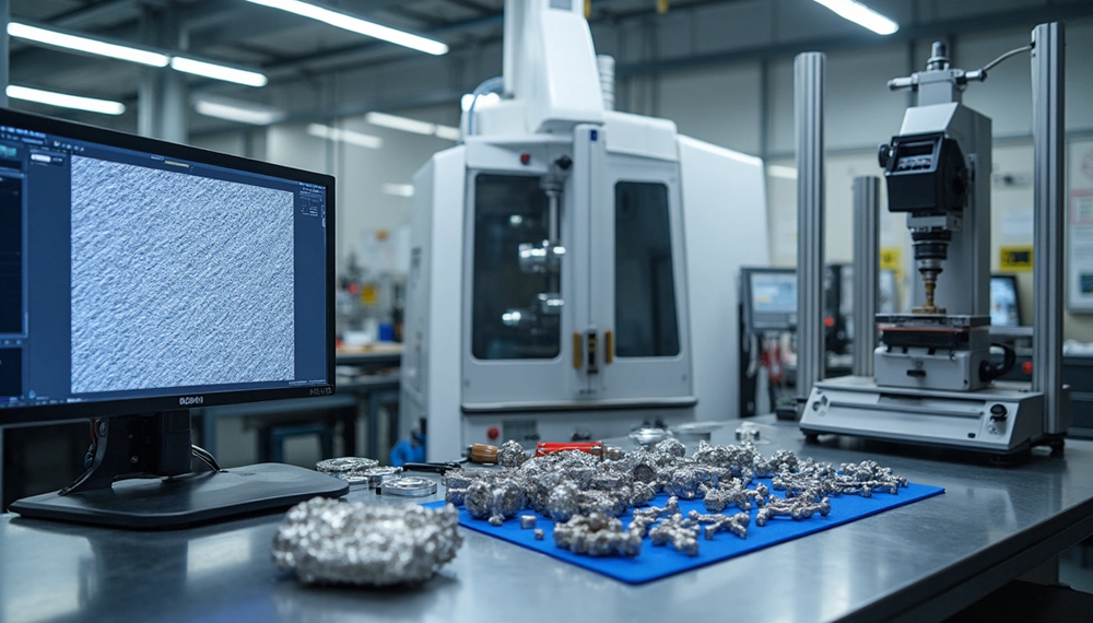
Microstructure Analysis via Optical and SEM Imaging
Metallographic examination forms the foundation to understand MIM component microstructures. Engineers review grain structure, porosity distribution, and inclusion content through optical microscopy. These elements directly affect mechanical properties. Scanning Electron Microscopy with Energy-Dispersive X-ray Spectroscopy (SEM-EDS) takes the analysis further with higher resolution and exceptional spatial resolution. This makes it a vital tool to analyze nanostructured materials and microscale features. The non-destructive analytical method keeps sample integrity intact and delivers qualitative and quantitative elemental analysis. SEM imaging detects elemental segregation or impurities at fracture surfaces and helps learn about failure mechanisms. MIM parts benefit from SEM-EDS as it identifies phase transformations and reviews powder particle distribution after sintering.
X-ray and CT Scanning for Porosity and Inclusion Detection
Industrial CT scanning creates complete 3D representations of MIM components without damaging them. Manufacturers can see both external and internal discrepancies with this technology. The process matches as-designed parts with as-manufactured ones to highlight warping from uneven shrinkage, incomplete fill in tight cavities, internal voids, and tool wear artifacts. Engineers can trace why problems occur—whether from mold design, process parameters, or material behavior—without cutting parts open. CT scanning helps the part design process too. Designers can see how real-life conditions affect geometry and performance when scanned models overlay CAD files.
Dye Penetrant Testing for Surface Crack Identification
Dye Penetrant Testing (DPT) is a budget-friendly way to detect surface-breaking flaws in MIM components. The process uses a penetrant liquid that seeps into surface defects. After removing excess penetrant, developers draw out any penetrant trapped in defects. Both ferrous and non-ferrous materials work well with this technique, including metals, plastics, and ceramics. DPT’s biggest advantage lies in its portability. It works without additional resources like electricity or water when using visible color contrast techniques.
Conclusion
Metallurgical testing is the lifeblood of quality assurance for Metal Injection Molding (MIM) components in vital industries. This piece has shown how MIM technology achieves remarkable density levels of 96-99%, which surpasses most other metal forming processes. The careful control of feedstock uniformity, binder composition ratios, and sintering temperature profiles determines the final part quality and performance.
Dimensional testing tools like coordinate measuring machines and 3D scanning verify that the 15-20% shrinkage during sintering stays within acceptable limits. These testing protocols ensure the geometric precision needed for complex medical devices and high-performance automotive parts. Mechanical tests through tensile, impact, microhardness, and fatigue testing confirm that MIM parts meet strict industry standards for strength, durability, and reliability.
Modern non-destructive techniques like CT scanning and SEM-EDS analysis have changed quality control for MIM manufacturing. These methods give detailed insights into external geometry and internal microstructure without damaging part integrity. While porosity remains a challenge in MIM processing, proper testing protocols can identify and alleviate these issues before parts go into service.
JH MIM brings nearly 20 years of expertise in Metal Injection Molding and Powder metallurgy. The company’s factories span more than 18000 square meters, with world-class equipment and 150 skilled workers who create precision-engineered products for customers worldwide.
Without doubt, these testing methods create a resilient quality assurance framework that keeps MIM’s competitive edge in producing complex, high-performance metal components. Companies that use detailed metallurgical testing protocols deliver better products while reducing production costs and improving manufacturing efficiency. MIM technology’s progress will drive these testing methods forward, which will expand this versatile manufacturing process’s capabilities and applications.
FAQs
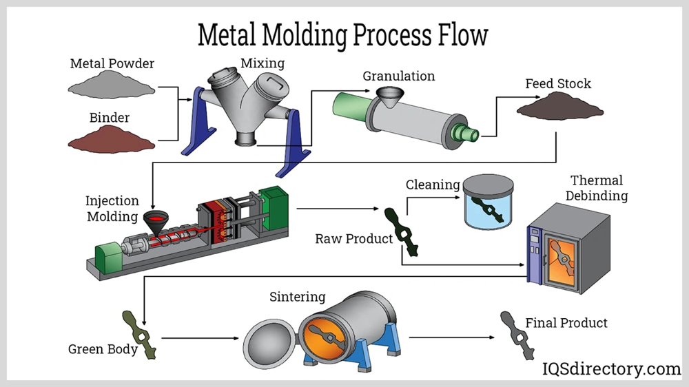
Q1. What are the key steps in the Metal Injection Molding (MIM) process? The MIM process involves four main steps: compounding metal powders with binders to create feedstock, injection molding the feedstock into desired shapes, debinding to remove the binder, and sintering to create a dense metal part. This process allows for the production of complex, high-precision metal components.
Q2. How does the density of MIM parts compare to other metal forming processes? MIM parts typically achieve an extraordinary density of 96-99%, which surpasses most other metal forming processes. This high density contributes to the superior mechanical properties and performance of MIM components.
Q3. What types of testing methods are used to ensure MIM part quality? Quality assurance for MIM parts involves various testing methods, including dimensional testing (using CMMs and 3D scanning), mechanical testing (tensile, impact, hardness, and fatigue tests), and advanced non-destructive techniques like CT scanning and SEM-EDS analysis for microstructure evaluation.
Q4. Are MIM parts suitable for magnetic applications? Yes, MIM parts can be suitable for magnetic applications, especially when made with soft magnetic materials. The high density achieved in the MIM process (around 98%) generally results in better magnetic performance compared to traditional powder metallurgy parts with the same materials.
Q5. What industries commonly use MIM parts? MIM parts are widely used in various industries including automotive, medical devices, electronics, aerospace, and consumer goods. They are particularly valuable for applications requiring complex geometries, high precision, and cost-effective high-volume production of small metal components.
References
[1] – https://www.optimim.com/resources/article/mim-series-part-2-feedstock
[2] – https://redstonemanufacturing.com/why-does-feedstock-particle-size-affect-mim-quality/
[3] – https://www.nelpretech.com/blog/closing-the-loop-how-ct-scanning-improves-mim-tooling-and-part-design
[4] – https://cjme.springeropen.com/articles/10.1186/s10033-023-00913-6
[5] – https://www.sciencedirect.com/science/article/abs/pii/S0924013607002907
[6] – https://assets.thermofisher.com/TFS-Assets/CAD/Application-Notes/LR69-e%20Mixer%20tests%20on%20MIM%20feedstock.pdf
[7] – https://www.mixer.co.uk/insights/mim-solutions/
[8] – https://vibgyorpublishers.org/content/ijmmp/ijmmp-3-022.pdf
[9] – https://www.newayprecision.com/services/metal-injection-molding/faq-what-is-the-shrinkage-of-metal-injection-molding
[10] – https://www.sigmatechnik.com/injection-molding/understanding-metal-injection-molding-shrinkage-benefits-and-strategies-for-successful-molding
[11] – https://www.zetwerk.com/resources/knowledge-base/metal-injection-molding/quality-control-and-inspection-techniques-metal-injection-molding/
[12] – https://jhmim.com/how-to-test-mim-part-quality/
[13] – https://hexagon.com/resources/resource-library/coordinate-measuring-machine-accuracy-shop-floor
[14] – https://www.qualitymag.com/articles/91768-measurement-accuracy-in-coordinate-metrology
[15] – https://www.zeiss.com/metrology/us/systems/optical-3d/3d-scanning.html
[16] – https://www.lumafield.com/article/manufacturing-process-metal-injection-molding-mim
[17] – https://www.instron.com/en/testing-solutions/astm-standards/the-definitive-guide-to-astm-e8-e8m/
[18] – https://www.pim-international.com/mim-316l-stainless-steel-mechanical-properties-compared-with-other-forming-processes/
[19] – https://www.struers.com/en/Knowledge/Hardness-testing/Vickers
[20] – https://www.buehler.com/blog/knoop-hardness-testing/
[21] – https://21145099.fs1.hubspotusercontent-na1.net/hubfs/21145099/Praxisti_March_2024/pdf/MPIF-2014-Titanium-MIM-Performance-and-Capability.pdf
[22] – https://www.jeolusa.com/NEWS-EVENTS/Blog/why-use-sem-eds-advanced-materials-analysis
[23] – https://www.intertek.com/non-destructive-testing/dye-penetrant-inspection/