
Engineering Main Bearing Caps: Manufacturing Microstructure, Materials, and Design Principles
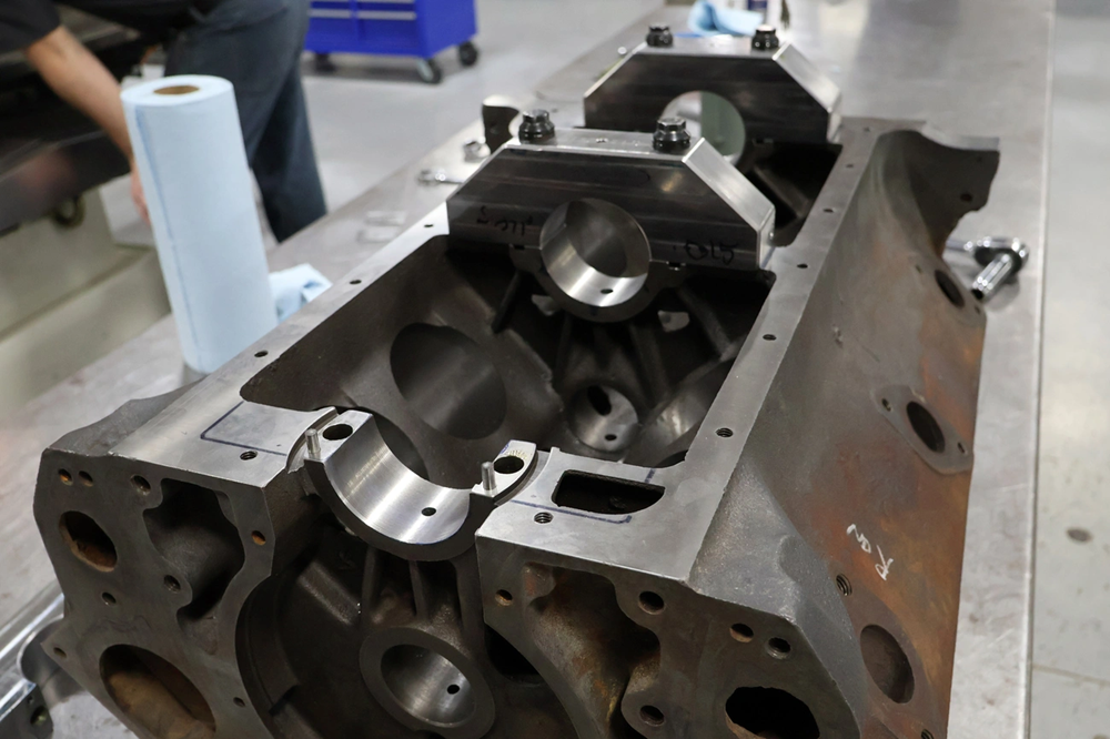
The main bearing cap serves as the structural anchor that secures the crankshaft to the engine block and withstands extreme cyclical loads during combustion. High-performance engines generally employ four-bolt or six-bolt designs to stabilize the crankshaft and prevent catastrophic bearing failure. Modern crankshaft bearing cap manufacturing uses powder metallurgy processes that achieve ultimate tensile strengths up to 480MPa. Billet steel main caps engine configurations offer superior resistance to flexing under high-rpm conditions. This piece gets into the manufacturing microstructure of engine bearing cap production and explores crankshaft main bearing cap material selection criteria. It details design principles governing bolt configurations, press fit requirements and precision machining tolerances for applications of all types.
Main Bearing Cap Functions and Load Requirements
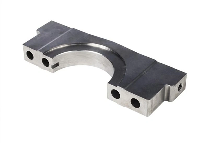
Main Bearing Cap Functions and Load Requirements
Crankshaft Support and Dynamic Load Distribution
Main caps engine assemblies distribute combustion forces through a complex load path that begins at the piston crown and ends at the engine block saddle. The crankshaft main bearing cap experiences both radial and tangential loads during each power stroke, and these loads fluctuate with engine speed and torque output. The crankshaft bearing cap prevents vertical displacement of the crankshaft journals. It maintains precise concentricity within the bearing saddle bore at the same time. Center main bearing positions experience higher loads than end caps in most cases because crankshaft deflection characteristics vary across cap designs. Offset connecting rod loads and torsional vibrations transmitted through the crankshaft assembly generate bending moments that the engine bearing cap must resist.
Clamping Force Retention and Oil Clearance Control
Fastener preload creates a clamping force that compresses the crankshaft main bearing cap against the block saddle. This establishes an interference fit between bearing shells and their respective bores. The clamping mechanism maintains consistent oil clearance tolerances between rotating journals and stationary bearing surfaces. Thermal expansion during operation introduces dimensional changes that affect oil film thickness. Calibration of the clamping force at the start prevents bearing shell micromotion. Proper torque specifications ensure the main bearing cap material remains within elastic deformation limits and provides adequate crush on bearing inserts.
Operating Stresses and Fatigue Behavior in High-Performance Applications
High-rpm operation creates cyclic stresses within bolt bosses and parting line interfaces of the main bearing cap assembly. Geometric discontinuities develop stress concentrations, especially around fastener holes and register fits. Fatigue cracks initiate at these stress risers after millions of load cycles. They progress through the main bearing cap material until structural failure occurs. High-performance applications just need materials with elevated fatigue strength limits and microstructures resistant to crack propagation.
Advanced Manufacturing Processes for Main Bearing Caps
Metal Powder Compaction and High-Density Green Part Formation
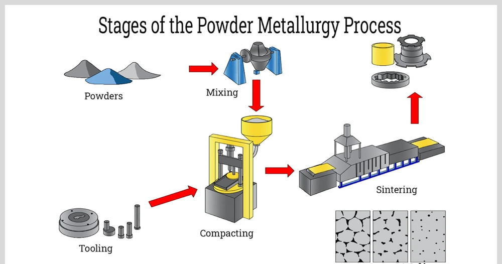
Blending iron-based metal powders with alloying materials and lubricants provides uniform density and strength characteristics. The powder mixture undergoes compaction in precision dies under high pressure and forms a green preform with the bearing saddle, bolt bosses, and cap geometry cast-in-place. Compaction pressures range from 10 to 45 tons per square inch and create a green part held together by mechanical interlocking. Green density refers to the powder’s solidness after compaction and influences material handling and subsequent sintering response. High-precision dies achieve reproducibility even for complicated shapes with tight tolerances.
Sintering Kinetics, Metallurgical Bonding, and Microstructure Control
Sintering transforms fragile green compacts into structurally sound components by heating the material to 70-90% of the metal’s melting point. Iron-based crankshaft bearing cap components sinter at approximately 1120°C. The process unfolds in three stages: original neck formation between particles, intermediate densification with isolated pore creation, and final pore shrinkage with grain growth. Atoms diffuse across particle boundaries and bond them into a solid mass while preserving microscopic voids. Sintering increases density and fatigue strength and provides rigidity to withstand crankshaft loads.
Advanced Machining: Fracture Splitting (Cracking) vs. Traditional Joint Line Milling
Fracture splitting separates the main bearing cap from the block saddle through controlled mechanical fracture rather than traditional cutting. Pre-machined stress concentration grooves guide crack propagation and create three-dimensional interlocking surfaces that are complementary and unique to each assembly. This interlocked topology provides passive shear resistance and prevents microscopic sliding under high-rpm loads. Traditional machining requires sawing, milling, and grinding operations with secondary face finishing.
Near-Net Shape Advantages and Material Utilization Yields
Near-net shape manufacturing produces components close to final dimensions and minimizes downstream processing. Powder metallurgy main bearing cap production achieves material utilization rates up to 97%, with almost 100% of material ending up in the final product. PM bearing caps require only one line-boring step during installation and translate into substantial cost savings.
Main Bearing Cap Material Selection and Metallurgy
Main Bearing Cap Material Selection and Metallurgy
Ductile and Gray Iron Caps: Mechanical Properties and Engineering Limitations
Gray iron features graphite flakes that provide good machinability and vibration damping. This makes it suitable for standard automotive applications. The flake structure acts as stress concentrators and results in brittleness with limited tensile strength. Ductile iron contains nodular graphite that delivers tensile strengths from 500 MPa in as-cast state to 1100 MPa after austempering. Ductile iron main bearing caps are a great way to get superior impact resistance. Elongation ranges between 4.6% and 11% depending on casting parameters. Gray iron excels in thermal conductivity and dimensional stability against thermal variations. Ductile iron provides the ductility needed for dynamic shock loads.
Powder Metallurgy Formulations: Balancing Density and Fatigue Strength Limits
PM crankshaft bearing cap formulations achieve ultimate tensile strengths up to 480 MPa through controlled density distribution. Density variations during sintering stay minimal at 0.2-0.3% for iron-based powders. PM materials balance lightweight design with fatigue resistance and offer good crack resistance under heavy crankshaft loads.
Billet Steel Caps: Ultimate Tensile Strength and Dimensional Stability
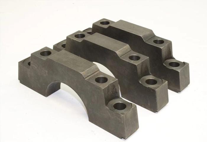
Billet steel main caps are manufactured from 1045 low carbon steel. They provide denser grain structure and greater stiffness compared to cast alternatives. Precision CNC machining produces consistent dimensions that maintain bearing clearances and reduce distortion under heavy loads. Dimensional stability prevents retained austenite transformation and martensite tempering at extreme temperatures.
Material Selection Matrix for Different Engine and Compressor Applications
Cast iron remains the reference material for standard engines. It balances budget-friendly production with structural strength. High-performance engines require billet steel for improved clamping force retention. Compressor applications prioritize materials with vibration absorption and thermal stability characteristics.
Design Principles and Geometric Specifications
Cap Geometry and Bolt Boss Wall Thickness Configuration
Bolt boss wall thickness requires dimensioning at about 60 percent of the nominal wall thickness to prevent sink marks and maintain strength under fastener clamping loads. Gussets or ribs improve boss strength and prevent stress-related cracking at the base intersection.
Fastening Systems: Two-Bolt vs. Four-Bolt Design Mechanics
Two-bolt crankshaft bearing cap designs work for naturally aspirated engines below 400 horsepower. Four-bolt configurations provide the clamping forces needed for high-output applications. Four-bolt main caps reduce cap walk and bearing bore distortion under extreme loads that exceed 6,000 rpm.
Press Fit Requirements and Register Tolerance Control
Press fit interference between the main bearing cap and block saddle ranges from 0.0005 to 0.002 inch for proper retention without excessive assembly force. Register depth should exceed block register depth by 0.001 to 0.003 inch. This creates controlled clearance that preloads the register and prevents cap movement.
Cross-Bolting and Splayed Bolt Configurations for Heavy-Duty Blocks
Cross-bolted bearings use fasteners positioned at 90 degrees to primary load direction and reinforce the crankcase against twisting forces. Splayed bolt designs anchor into the block sidewall rather than the main web. They provide improved structural support for engines that generate 500 horsepower and above.
Precision Boring: Controlling Saddle Roundness, Cylindricity, and Surface Roughness
Cylindricity tolerance establishes two concentric cylinders that define the acceptable deviation zone for bearing saddle bores. Align boring machines restore proper saddle diameter and centerline alignment after cap installation. They maintain concentricity across all bearing journals.
Partner with Us for Custom Precision Main Bearing Cap Manufacturing
IATF 16949 Certified Production Infrastructure and Advanced CNC Boring Tolerances
Manufacturing facilities operating under IATF 16949 certification demonstrate compliance with automotive industry quality management systems. These systems emphasize defect prevention and traceability. This certification combines original equipment manufacturer requirements into a unified standard that international automotive supply chains recognize. Climate-controlled production environments prevent thermal expansion during machining of temperature-sensitive components. CNC operations achieve precision tolerances of ±0.003 mm as a result. Advanced boring equipment maintains saddle roundness within IT5 to IT6 tolerance grades. The equipment delivers surface finish specifications of Ra 0.8 micrometers for shaft seats and Ra 1.6 micrometers for housing bores. These surface finish parameters prevent uneven load distribution that accelerates bearing failure modes.
Conclusion
Modern crankshaft bearing cap engineering combines advanced powder metallurgy processes and precise material selection to deliver reliable performance under extreme combustion loads. Manufacturing advancements like fracture splitting and near-net shape production achieve material utilization rates approaching 97%. IATF 16949 certified facilities maintain tolerances within ±0.003 mm. Proper material selection paired with four-bolt configurations and precision boring techniques will give dimensional stability in a variety of applications. These range from standard automotive engines to high-performance compressor assemblies that demand superior fatigue resistance.
Submit Your Component Drawings and Material Specs for a Free DFM Feasibility Review
Design for Manufacturing analysis bridges the gap between engineering intent and production realities. Manufacturing experts participate during the design phase. Feasibility reviews confirm supplier capacity and equipment availability for specific crankshaft bearing cap geometries. They identify potential scaling bottlenecks before full production commitment. Engineering teams receive feedback on part complexity and tolerance specifications to refine tooling specifications. The specifications arrange with production capabilities through this process. This collaborative approach prevents late-stage discoveries regarding manufacturability constraints or prohibitive tooling costs.
Main bearing caps are fastened to the engine block using high-strength bolts in various configurations. Standard engines typically use two-bolt designs, while high-performance engines employ four-bolt or even six-bolt configurations to provide additional rigidity and better stabilize the crankshaft under extreme loads.
The main bearing cap creates a stable mounting seat for the crankshaft installation. This stability is essential for maintaining proper crankshaft alignment and preventing abnormal wear that could compromise overall engine operation and performance.
Engineering design for bearing caps involves applying scientific and mathematical principles to create practical solutions. Key principles include designing for functionality, safety, reliability, and manufacturability, ensuring the component can withstand dynamic loads while being cost-effective to produce.
Main bearing caps are manufactured from various materials including gray iron, ductile iron, powder metallurgy formulations, and billet steel. Each material offers distinct advantages—gray iron provides excellent machinability, ductile iron offers superior impact resistance, powder metallurgy achieves high material utilization, and billet steel delivers maximum tensile strength and dimensional stability.
Fracture splitting separates the bearing cap from the block saddle through controlled mechanical fracture rather than cutting. This process creates unique three-dimensional interlocking surfaces that provide passive shear resistance and prevent microscopic sliding under high-rpm loads, unlike traditional machining which requires sawing, milling, and grinding operations.