Hypoid gear advantages and disadvantages
Hypoid gear is a deviation from bevel gear, hypoid gear originated from the special development of the automobile industry. Can increase the diameter of the small wheel, easy to achieve double span support, using the small wheel lower offset, can reduce the center of gravity is comfortable car. Using the offset on the small wheel can make the off-road vehicle more powerful. Looks a lot like a spiral bevel gear. However, it is complex in design and most difficult to produce on bevel gear generators.
Tooth shape characteristics of hypoid gear
Smoothness: The tooth shape of a hypoid gear is surrounded by two perpendicular surfaces. This curved shape can effectively reduce the contact deformation of the gear mesh, thereby improving the transmission accuracy and operation. At the same time, the tooth shape of the hypoid gears can also make the change of the mesh Angle of the two wheels smoother, reduce the impact and vibration in the transmission, and reduce the noise of the gear.
Stability: Hypoid gears have higher transmission efficiency, less tooth surface contact fatigue and deformation, less tooth surface wear, better lubricity, lower noise and improved transmission stability compared to other transmission devices.
High precision: hypoid gears have characteristics that are difficult to match with ordinary gears, so they have been successfully applied in some fields. For example, ultra-precision instruments such as astronomical telescopes, as well as high-performance mechanical equipment such as high-speed trains, power ships, spacecraft, and machine tools. They all require a high degree of accuracy and reliability, and hypoid gears just meet this need.
Advantages Of Hypoid Gear
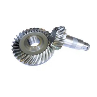
In the front-drive model, the main reducer is generally composed of two cylindrical gears; On the front and rear drive models, the main reducer is composed of a set of bevel gears, and its biggest feature is that it can change the direction of power transmission by 90 degrees. According to the different models, the main reducer drive gear can be generally divided into straight bevel gear, spiral bevel gear and hypoid gear (commonly known as hyperbolic gear) three kinds. Hypoid gear is the most widely used one
The main characteristic of hypoid gear is that the driving bevel gear axis of hypoid gear is offset to a certain degree from the driven gear axis, which is different from spiral bevel gear. It can reduce the position of the active bevel gear and drive shaft, so that the body and the center of gravity of the vehicle are reduced, which is conducive to improving the driving stability of the car; The offset of the gear also makes the number of teeth of the driving gear can be less, and a pair of gears can obtain a larger transmission ratio; The overlap coefficient of the hyperboloid gear meshing is relatively large, the working strength is higher, the carrying capacity is large, the noise is smaller, the transmission is more stable, and the service life is long.
Disadvantage Of Hypoid Gear
Hyperboloid gear also has some disadvantages, that is, when hypoid gear works, there is a large relative slide between the tooth surfaces, and its movement is both rolling and sliding, so the pressure between the tooth surfaces is large, and therefore the lubricating oil is very high. In use, special attention should be paid to only the special hypoid gear oil, and the use of ordinary gear oil is prohibited, otherwise it will be damaged by rapid and severe wear of the tooth surface. In practice, we have encountered many faults that cause abnormal wear of the main reducer due to adding wrong gear oil.
Hypoid gears have strict requirements for meshing clearance and meshing marks of gears. The general mesh clearance standard is 0.15~0.40mm. The mesh mark should reach more than 50% of the tooth length, and the position is controlled in the middle of the small end of the tooth, 2~4mm from the small end. The meshing impression in the direction of the tooth height should be greater than 50% of the effective tooth height, and 0.8~1.6mm from the top of the tooth.
Various Gears
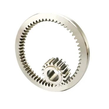
Internal gear: gear design in which the teeth of one gear are embedded into the interior of another gear, often used to improve torque transfer efficiency and reduce gear size.
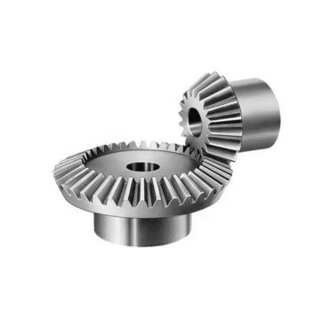
Bevel gear: a pair of gears whose working surface is inclined to a non-parallel axis.
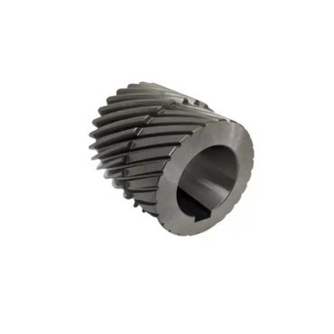
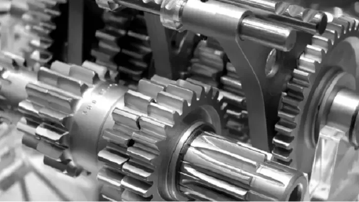
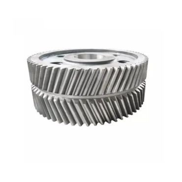
Cylindrical gear is an important type of gear in mechanical gear, and it is the most common type of gear. Cylindrical gear according to the direction of the gear teeth, can be divided into straight gear, helical gear and double-helical gear.

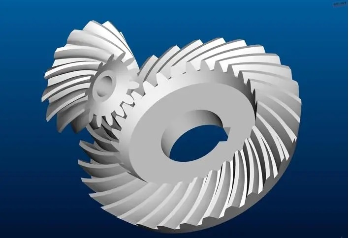
Helical gear, the most common spiral bevel gear and hypoid gear, has been used in many industrial fields, especially in the automotive industry. Helical gear is one of the main parts of the mechanical transmission system, its tooth surface structure is complex, the structure of the cutting machine tool and its processing adjustment is the most complex, while the processing tool, machine parameter setting, loading deformation and assembly errors will cause its meshing, bearing and vibration performance changes, making the helical gear in the design and manufacturing quality control is extremely difficult.
Hypoid gear is also known as “altitude gear”. The conical surface is used as the indexing surface to replace the falling wheel of the end truncated surface away from the throat on the hyperbolic body.
Helical gear has a transverse force on the shaft, in order to eliminate this force, a gear is made into a symmetrical helical gear in the opposite direction to eliminate this force, which looks like a personal word, referred to as Herringbone Gear.
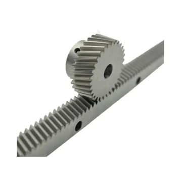
A pair of gears, consisting of a round pinion and a straight bar rack, used to convert rotational motion into linear motion; It is used in the steering mechanism of automobiles and in some railways.
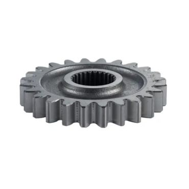
A straight tooth is a type of Gear, Spur Gear. According to the relative position of the axis of a pair of gears and the tooth direction (whether the two weeks are parallel or not), it can be divided into plane gear rotation and space gear rotation. According to the different working conditions of the gear can be divided into open drive and closed drive; According to the shape of the tooth or tooth profile, it is divided into straight teeth, oblique teeth, herringbone teeth, or straight teeth, curved teeth.
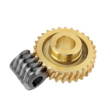
Worm gear is commonly used to transmit motion and power between two staggered axes. Worm gear and worm are equivalent to gear and rack in the middle plane, and worm and screw are similar in shape. The gear reduction ratio of worm gear is generally 3:1~100:1.
Yes, this is a routine operation for most companies before making an inquiry.
We have metal 3D printing equipment and can provide sample 3D printing.
3D drawings allow engineers to better understand the structure of the product, and 2D documents can provide more information, including materials, tolerances, surface treatment, etc. More detailed information is conducive to more accurate quotation by engineers.
In the case of detailed inquiry drawings and information, it usually only takes 2-3 days for us to give you a detailed quotation, including product price and mold price.
After confirming the order, we usually take 5-7 days to prepare the DFM report of the product. After confirmation, we spend 25 days to complete the mold, and provide T1 samples to customers for testing in the following 10-15 days.
If there is a problem with the test, we will re-sample it for free based on the feedback and provide a suitable sample.
MIM products MOQ 2000 PCS,
CNC products MOQ 2000 PCS,
Alu die casting, MOQ 2000 PCS
PM product MOQ 5000 PCS
Typically, the lead time for processing and submitting samples is 30 days. However, according to the order quantity and special requirements of customers, we can extend or shorten the delivery cycle accordingly.
1-year product warranty
World-class testing equipment
30+QC Workers
Key sizes 100% checking before shipment
ISO9001+IATF16949
Usually T/T is used as the payment method
Mold: 50% deposit, 50% payment after confirming the sample.
Bulk production: 30% deposit, 30% see bill of lading Copy, pay 70% balance.