
Did you know MIM parts reach an amazing 96-99% density that surpasses most other metal forming processes by a lot?
Metal Injection Molding (MIM) has revolutionized the production of complex metal components, particularly for small parts ranging from 0.1g to 200g. The process achieves impressive precision, with typical tolerances of ±0.3% after sintering, but it also presents its quality control challenges. The parts shrink 15-20% during sintering, and manufacturers must factor this in their original designs. Quality testing becomes vital for MIM metal components to meet strict standards in a variety of high-performance applications from medical to automotive and electronics sectors. Manufacturers need to verify both internal and external geometries and detect defects like porosity that could affect performance.
Understanding What Affects MIM Part Quality
MIM parts’ quality depends on several factors during manufacturing. Each stage, from raw materials to final sintering, needs tight control to get the best results.
Material consistency and feedstock preparation
Quality MIM parts start with proper feedstock preparation. This vital first step combines fine metal powders with a thermoplastic binder system. Metal powders are usually 4 to 25 microns in size, and the powder-to-binder ratio ranges from 60:40 to 70:30 by volume. The particle size distribution affects:
- How does material flow during injection
- The part’s final density
- Mechanical properties after sintering
The feedstock’s quality relies on how well metal particles mix with the binder. A well-prepared feedstock flows smoothly and has the right properties to mold properly. Any mix problems can create defects in the final product. Different material batches might cause parts to deform during sintering, so quality control becomes essential.
Tooling precision and mold design
The tooling’s precision determines what tolerances MIM parts can achieve. Quality molds need materials like H13, S7, and A2 tool steels that can handle high temperatures and pressures during injection.
Even wall thickness helps prevent sink marks and warping. The gate design shapes how molds fill and affects green part consistency. Modern mold flow simulation helps place gates for balanced filling and reduces trapped air.
The gate’s size, shape, and location change how feedstock flows into the mold cavity. These factors then affect how consistent green parts are before debinding and sintering.
Sintering and shrinkage control
Sintering turns the brown part into solid metal by carefully controlling temperature in a protective atmosphere. This happens at temperatures just below the metal’s melting point and usually shrinks parts by 15-20%.
Parts need controlled shrinkage during sintering to stay accurate. Pre-alloyed powders, good binder burnout, and exact sintering temperature profiles help keep shrinkage consistent between parts. Even heating rates, steady temperatures, and proper cooling reduce distortion and optimize final dimensions.
The sintering environment also affects quality—different atmospheres control oxidation and reduction reactions. Parts need good support during sintering to avoid warping, especially with complex shapes and thin walls.
Visual and Dimensional Inspection Techniques
Quality control teams need systematic methods to check finished MIM parts. They must verify both external appearance and dimensional accuracy. The success of quality control depends on picking the right inspection method for each quality parameter.
Visual inspection for surface defects
Skilled operators start by looking for surface defects like cracks, voids, burrs, and discolorations in MIM components. This basic inspection technique remains vital to spot visible flaws, even though it’s subjective. Quality teams do this work under controlled lighting conditions and check each part thoroughly. The results vary based on the operator’s experience, which makes it hard to keep standards consistent.
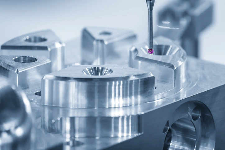
Using CMM for dimensional accuracy
Coordinate Measuring Machines (CMMs) check critical dimensions and tolerances with incredible precision. These advanced systems collect detailed measurements through touch-probe technology that moves along three Cartesian axes (X, Y, and Z). CMMs excel at taking accurate measurements down to the micrometer level. This helps ensure complex MIM geometries match exact specifications.
CMM technology is a great way to boost quality assurance. It lets teams spot defects immediately before they affect more production parts. This precision is significant for MIM manufacturers because they need tight control over post-sintering dimensional tolerances.
When to use 3D scanning or CT
3D scanning works best for MIM parts with complex organic shapes that regular measuring tools can’t handle well. The technology captures thousands of data points in minutes instead of hours.
Computed tomography (CT) scanning is a chance to find internal defects without damaging MIM components. This non-destructive inspection technique creates detailed 3D views of both external and internal structures in one scan. CT scanning finds and measures internal problems like porosity, voids, and inclusions that could affect performance. Manufacturers can use this data to improve their MIM process and cut down on waste.
Mechanical and Structural Testing Methods
Mechanical testing of MIM components reveals performance characteristics that visual inspection cannot detect. These tests generate data that shows how parts perform in real-life conditions.
Tensile and impact strength tests
Tensile testing measures key mechanical properties of MIM parts according to ASTM standards. The test applies increasing tensile force until the specimen fails. This generates stress-strain curves that show ultimate tensile strength, yield strength, and elongation. MIM titanium alloys like Ti-6Al-4V deliver impressive tensile properties. This is a big deal as it means that ultimate tensile strength reaches 800 MPa with elongation above 15%.
Charpy V-notch tests measure how materials absorb energy before breaking. These tests explain toughness and impact energy in MIM components. Scientists have found links between fracture toughness (KIC) and Charpy impact energy values. This allows a complete material assessment.
Hardness testing for wear resistance
Hardness tests show how materials resist permanent deformation by measuring indentation depth or impression size. Common methods include:
- Rockwell: Fast production control test with direct readout
- Vickers: Versatile test applicable to all solid materials
- Knoop: Alternative for brittle materials and thin layers
- Brinell: Used for larger samples with coarse-grain structures
Microhardness testing uses loads of 1 N or less. This proves valuable when perusing MIM parts that have varying properties throughout their structure.
Fatigue and pressure testing for durability
Fatigue testing shows how MIM components handle cyclic stresses. Four-point bending setups work well because they fit simple geometries that MIM technology can process. MIM parts typically show lower fatigue strength than standard manufactured components due to coarser microstructure and residual porosity.
Pressure testing confirms component integrity under specific pressure conditions. Components undergo controlled pressurization while monitors check for leaks or failures. This test becomes crucial for MIM components designed to handle fluids or pressure applications.
Advanced Analysis and Non-Destructive Testing
Advanced analytical techniques show critical aspects of MIM parts that standard testing methods cannot detect. These specialized approaches give a full picture of internal structures and surface integrity.
Microstructure analysis under the microscope
Metallographic examination is the lifeblood of microstructural analysis for MIM components. The process scrutinizes polished cross-sections under optical or electron microscopes to assess grain structure, porosity distribution, and inclusion content. A component’s final mechanical properties are associated directly with this analysis. It shows how well the sintering process achieved material densification. Microstructural analysis identifies potential risks like excessive porosity or improper phase transformations that could hurt part performance. Many companies use automated image analyzers to assess grain size, shape, and distribution based on ASTM standards.
X-ray and CT scanning for internal flaws
X-ray and computed tomography (CT) scanning techniques let you see inside a MIM part’s structure without destroying it. CT scanning creates detailed 3D representations of components while keeping them intact. This technology spots internal defects such as voids, inclusions, and porosity that might stay hidden otherwise. CT scanning is a great way to get insights for complex MIM parts by creating a “digital twin” that engineers can analyze from any angle. The technology helps make MIM processes better by finding inconsistencies in material flow or density during sintering. This reduces scrap rates and improves part quality.
Dye penetrant testing for surface cracks
Dye penetrant testing (DPT) is the quickest way to find surface-breaking flaws in MIM components. The process works like this:
- Clean the part’s surface well
- Apply a specialized dye that seeps into surface defects
- Remove extra dye from the surface
- Apply a developer to pull out the penetrant from the defects
This technique reveals cracks, porosity, and other discontinuities through capillary action effectively. DPT works well on both ferrous and non-ferrous MIM parts of all types, which makes it useful for MIM materials across the board.
Conclusion
Testing MIM Parts: Essential for Quality Assurance
Quality control plays a vital role in every step of the MIM manufacturing process. Each phase, from feedstock preparation to final testing, affects the component’s performance by a lot. Manufacturers must put in place complete testing protocols to verify both dimensional accuracy and material integrity.
Visual inspection, precision measurement, and advanced non-destructive testing create a strong quality assurance framework. On top of that, it needs mechanical testing to show how MIM parts perform in real-life conditions. This layered approach catches potential defects before parts reach end-users.
The choice of testing methods depends on specific application needs. High-stress applications need tensile and fatigue testing especially when you have critical performance requirements. Parts with complex internal geometries work best with CT scanning capabilities.
JH MIM brings nearly 20 years of expertise in Metal injection molding and Powder metallurgy. The company’s facilities span more than 18000 square meters, equipped with world-class machinery. Their team of 150 skilled workers delivers precision-engineered products to customers worldwide.
A deep grasp of these testing methods helps manufacturers create high-quality MIM components that meet exact specifications consistently. MIM manufacturing involves complex processes with many variables. Yet proper testing gives reliable performance whatever application challenges arise. Quality control isn’t just a final checkpoint – it’s a steadfast dedication throughout the manufacturing journey.
FAQs
Q1. What are the key factors affecting MIM part quality? The quality of MIM parts is influenced by material consistency, feedstock preparation, tooling precision, mold design, and sintering process control. Proper management of these factors is crucial for achieving optimal part density, dimensional accuracy, and mechanical properties.
Q2. How is dimensional accuracy verified in MIM parts? Dimensional accuracy in MIM parts is primarily verified using Coordinate Measuring Machines (CMMs). These sophisticated systems use touch-probe technology to capture detailed dimensional data with micrometer-level precision, ensuring complex MIM geometries meet exact specifications.
Q3. What mechanical tests are commonly performed on MIM components? Common mechanical tests for MIM components include tensile strength tests, impact strength tests (like Charpy V-notch), hardness testing, and fatigue testing. These evaluations provide critical data on how parts will perform under real-world conditions.
Q4. How can internal flaws in MIM parts be detected without damaging the component? X-ray and computed tomography (CT) scanning are non-destructive techniques used to detect internal flaws in MIM parts. CT scanning, in particular, creates detailed 3D representations of components, revealing internal defects such as voids, inclusions, and porosity without damaging the part.
Q5. What is the typical density achieved in MIM parts? MIM parts typically achieve a density of 96-99%, which is significantly higher than many other metal forming processes. This high density contributes to the near-wrought properties of MIM components, making them comparable to parts produced by traditional forging or machining methods.
Pingback: What Modern Industries Rely on Powdered Metal Parts Manufacturers?