Metal parts shrink by 15-20% as particles fuse during the Metal Injection Molding process.
This shrinkage creates major engineering hurdles. Parts can fail, develop surface defects, lose mechanical strength, and become dimensionally inaccurate if shrinkage isn’t factored in properly. Therefore, understanding and controlling this shrinkage becomes vital, especially in industries that require high-performance metal components. Medical devices, electronics, firearms, and automotive parts are prime examples.
Uniform wall thickness helps ensure even shrinkage and reduces warping. The thickness usually ranges between 1-6mm based on part size. Material choice, processing settings, and mold design substantially affect the final results. Manufacturing teams need detailed plans to predict, measure, and adjust these shrinkage defects. This piece offers practical ways to control part shrinkage and deliver precise results consistently.
What Causes Shrinkage in Injection Molding?

Shrinkage happens naturally in injection molding when plastic cools from its molten state to a solid form. Engineers need to know why it happens to control dimensions precisely and avoid defects.
Material behavior during cooling
The plastic type you choose affects how much shrinkage occurs. Semi-crystalline materials like polyethylene and polypropylene shrink more than amorphous materials such as polystyrene or polycarbonate. This happens because crystalline structures pack themselves tightly during cooling and take up less space.
A polymer’s molecular weight plays a vital role. Polymers with higher molecular weight become more viscous and lose pressure in the mold cavity. This can lead to more shrinkage if not handled properly. The material’s additives can substantially change how it shrinks. Glass fiber fillers reduce shrinkage based on how much you add. Talc and copper fillers change heat transfer differently – materials with 30% talc show the best heat transfer properties.
Impact of mold design and geometry
The thickness of walls directly shapes shrinkage patterns. Thicker sections cool slower and create denser solid layers that might shrink more. When you double the wall thickness, the cycle time can increase four times. This shows how much geometry can affect cooling.
The size and location of gates matter just as much. Larger gates usually cause less shrinkage but make it more directional. The cooling channel layout determines how evenly heat leaves the mold. Poor cooling system design creates hot and cold spots that lead to warping as different areas shrink at their own rates.
Processing parameters and their role
The mold’s temperature has a big effect on shrinkage rates. Warmer molds let molecules move more freely and shrink less than cold molds. The injection pressure also matters – higher pressure packs material tighter and reduces shrinkage.
Holding pressure and time are the most important processing factors. The holding phase makes up for shrinkage by forcing more material into the cavity. Too little holding pressure leads to excess shrinkage and unstable dimensions. The cooling time depends mostly on how thick the material is and the mold temperature. This usually takes up two-thirds of the total cycle time.
The cooling medium’s performance helps control shrinkage. Research shows that cooling water with ultrafine bubbles works 12.4% better than regular cooling water.
The mold material you pick changes the cooling time. Different mold materials can change cooling times by up to 99 seconds – this matters more than picking the right cooling medium. Machine settings like injection speed and consistency change how the mold fills and how pressure spreads, which ends up affecting shrinkage in different areas.
How Shrinkage Affects Part Quality

Shrinkage defects seriously affect part quality in many ways. These problems go beyond simple size differences.
Dimensional inaccuracies and tolerance issues
Parts that shrink without control show dimensional inconsistencies and fail to meet design specifications. This directly affects how parts fit together. Assembly failures happen even with tiny inaccuracies in precision applications. Parts with wrong dimensions can’t seal properly in automotive or electronic components. This leads to high rejection rates during quality checks.
Different materials show varying levels of dimensional stability. Crystalline resins tend to shrink more and show more variation than non-crystalline options. Quality control becomes difficult because shrinkage varies between cavities or batches, even with the best equipment.
Warping, distortion, and surface defects
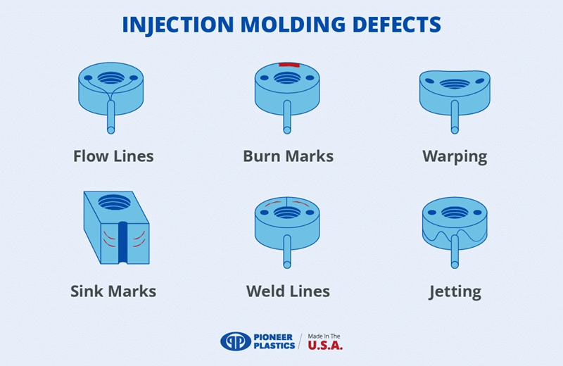
Warpage stands out as the most visible quality problem in injection molding. Parts deform because shrinkage isn’t uniform across different areas. This creates internal stresses that the part’s structure can’t handle. Warpage shows up in four main ways: between gate and end-of-fill areas, through opposite surfaces, along versus across flow, and differences between plane and thickness.
The surface can show sink marks and dips, especially in thick walls or hot spots like bosses and ribs. While sink marks might not weaken the part, they make it look bad and reduce the product’s perceived quality.
Mechanical property degradation
Uneven shrinkage creates stress points that make parts weaker and less tough. The shrinkage continues after molding through secondary crystallization. Research shows that tensile strength goes up 7% for parts made at 20°C mold temperature and 5% at 80°C after 168 hours.
This post-molding crystallization makes parts more brittle. The elongation at break drops from 176% to 67.6% for parts molded at 20°C. Impact strength also gets worse – the absorbed energy falls from 183J to 94J after 504 hours.
Best Practices to Control Shrinkage

Injection molding shrinkage control needs a methodical approach that looks at material properties, design elements, and processing variables. You can manage shrinkage effects by taking specific steps at each production stage.
Choose materials with predictable shrinkage
Material choice serves as the cornerstone of shrinkage control. Amorphous polymers like polycarbonate or polystyrene show lower and more uniform shrinkage than semi-crystalline materials such as polyethylene and polypropylene. Applications that need tight tolerances work best with filled grades or materials having low crystallinity. Glass fibers or minerals as fillers reduce shrinkage and might cut down material costs. Talc or mineral fillers will give you lower shrinkage rates while boosting stiffness.
Design for uniform wall thickness
Wall thickness uniformity ranks as the key design factor to control shrinkage. Your walls should measure between 1.2mm and 3mm, and adjacent walls need to keep 40-60% thickness relative to each other. Core out thick sections in parts to keep overall uniformity, since thicker walls create longer cooling times and raise shrinkage potential. Uniform, thinner walls resist warping as they cool and need less processing time.
Optimize gate placement and cooling channels
Gate location shapes shrinkage patterns and part quality. Smart gate positioning prevents weld lines, dents, flash, and warpage. Place gates at thick sections to maximize part packing and avoid sink marks. Conformal cooling channels cut cooling time from 19.18 seconds with standard channels to 7.205 seconds with optimized designs. Well-placed cooling channels give you even temperature distribution and minimize differential shrinkage.
Use simulation tools to predict shrinkage
Engineers can spot shrinkage issues before production starts with simulation software. CADMOULD or Moldex3D help predict filling patterns, packing effectiveness, and possible warpage. These tools show how parameter changes affect outcomes, letting you make analytical adjustments instead of trying costly trial-and-error methods. Running multiple design variants side by side helps engineers find better solutions with less guesswork.
Adjust processing parameters like pressure and hold time
Processing parameters play a vital role in shrinkage control:
- Holding pressure: Keep enough pressure to offset material shrinkage during cooling. Low holding pressure causes too much shrinkage, unstable dimensions, and surface defects.
- Mold temperature: Higher mold temperatures create more uniform shrinkage but take longer cycles. Temperature controllers keep the mold consistent throughout.
- Packing time: Your holding time should last until the gate solidifies—about 30% of cooling time.
Smart adjustments to these parameters help you achieve the best dimensional accuracy without creating new defects.
Measurement and Validation Techniques
Precise measurement is the life-blood of managing shrinkage issues in injection molding processes. Engineers use validation techniques to identify, measure, and adjust dimensional changes throughout production.
Using coordinate measuring machines (CMM)
CMMs are the foundation of shrinkage measurement in injection molding. Engineers calculate shrinkage by comparing mold cavity dimensions with molded part dimensions at specific points to find the difference. This method gives precise shrinkage rates, shown as thousandths of an inch per linear inch (0.00X /in/in) or as a percentage. Shrink rates typically range between 0.001/in/in and 0.020/in/in based on material properties and processing conditions. CMMs deliver accurate readings with error margins as precise as ±0.0002 cm/cm.
CT scanning for internal defect detection
CT scanning offers complete three-dimensional visualization without destroying parts, unlike traditional measurement methods. The technology creates a digital model from thousands of X-ray images as the part rotates. This model can be electronically sliced at any angle. CT scans show remarkably fine details and can detect ejector-pin marks or even transfer of cutter marks from the tool cavity. CT scanning’s repeatability reaches nearly perfect levels (97-99.5%), while CMM measurements often vary due to operator technique.
Shrinkage compensation in mold design
Mold design starts with applying a shrinkage allowance to address potential issues. Tooling engineers scale mold dimensions according to the material’s expected shrinkage rate. Better shrinkage compensation reduces the number of try-outs needed to achieve specified tolerances. Modern mold designs now include built-in compensation through adjusted cavity size and geometry.
Monitoring shrinkage trends over production runs
Quality control depends on long-term shrinkage monitoring. Statistical process control helps engineers track dimensional stability in production runs. Optical fiber sensors in the mold cavity wall provide up-to-the-minute shrinkage data during molding. These sensors detect when resin separates from the mold wall as materials cool. They generate interference fringes that measure shrinkage. This technique identifies non-uniform stress distribution that might lead to warpage.
Conclusion
Quality and precision in injection molding processes depend on proper shrinkage control. Engineers who know the basic mechanisms of shrinkage can apply strategies to alleviate its negative effects. The right material choice is where it all begins – amorphous polymers show more predictable shrinkage patterns than semi-crystalline ones.
Parts with uniform wall thickness help reduce uneven shrinkage that causes warping and distortion. Smart gate placement and optimized cooling channels boost dimensional stability by creating consistent material flow and heat removal.
Simulation tools will give a great way to get feedback before production starts. Engineers can spot potential shrinkage problems early in design. The best results come from adjusting processing parameters like holding pressure, mold temperature, and packing time during production.
Accurate measurement plays a vital role in validation. Modern coordinate measuring machines and CT scanning give precise ways to calculate shrinkage effects. Regular monitoring ensures quality stays consistent across production runs.
Manufacturers who use complete shrinkage control strategies can make parts with better dimensional accuracy, structural integrity, and visual appeal. This systematic approach cuts down scrap rates and production costs. It also improves product performance and customer satisfaction. Knowing how to predict, control, and adjust for shrinkage helps distinguish successful injection molding operations from those with quality problems.
Key Takeaways
Understanding and controlling shrinkage is critical for achieving precision in injection molding, as uncontrolled shrinkage leads to dimensional inaccuracies, warping, and mechanical property degradation that can cause part failure.
• Material selection is fundamental – Choose amorphous polymers over semi-crystalline materials for predictable shrinkage, and use filled grades to reduce shrinkage rates.
• Design for uniform wall thickness – Maintain 1.2-3mm wall thickness with adjacent walls at 40-60% relative thickness to prevent uneven shrinkage and warping.
• Optimize processing parameters strategically – Adjust holding pressure, mold temperature, and packing time to compensate for material shrinkage during cooling phases.
• Use simulation tools before production – Predict shrinkage patterns and potential defects early in the design process to avoid costly trial-and-error approaches.
• Implement precise measurement techniques – Deploy CMM and CT scanning for accurate shrinkage quantification, and monitor trends across production runs for consistent quality.
Successful shrinkage control requires a systematic approach combining smart material choices, thoughtful design principles, optimized processing parameters, and rigorous measurement validation to achieve superior dimensional accuracy and part quality.
FAQs
Q1. What are the main factors that cause shrinkage in injection molding? Shrinkage in injection molding is primarily caused by material behavior during cooling, mold design and geometry, processing parameters, and environmental factors. The type of plastic used, wall thickness variations, gate design, mold temperature, and injection pressure all play significant roles in determining shrinkage rates.
Q2. How does shrinkage affect the quality of injection molded parts? Shrinkage can lead to dimensional inaccuracies, warping, surface defects like sink marks, and degradation of mechanical properties. These issues can result in assembly problems, reduced structural integrity, and overall lower part quality.
Q3. What are some best practices for controlling shrinkage in injection molding? Key practices include choosing materials with predictable shrinkage behavior, designing parts with uniform wall thickness, optimizing gate placement and cooling channels, using simulation tools to predict shrinkage, and adjusting processing parameters like pressure and hold time.
Q4. How can engineers measure and validate shrinkage in injection molded parts? Engineers can use coordinate measuring machines (CMM) for precise dimensional measurements, CT scanning for internal defect detection, and implement shrinkage compensation in mold design. Additionally, monitoring shrinkage trends over production runs helps maintain consistent quality.
Q5. Why is controlling shrinkage important in injection molding? Controlling shrinkage is crucial for achieving dimensional accuracy, preventing defects, and ensuring the structural integrity of molded parts. It helps reduce scrap rates, lower production costs, and improve overall product performance and customer satisfaction.
