Die Casting Design
Pressure casting (also known as die casting) is a type of special casting procedure that is continuously evolving in modern metal forming processing technology. The principle of the process is that the liquid or semi-liquid metal fills the die casting chamber at a high rate under the action of high pressure, and the casting is produced and solidified under pressure.
Die casting process characteristics: The major aspects of pressure casting are fast speed and high pressure. The usually utilized working pressure is tens of mpa, the filling speed is approximately 1680m/s, and the metal filling period of the mold cavity is extremely short, approximately 0.010.2s.
Main advantages of die casting:
- Excellent product quality
The casting’s dimensional accuracy is good, often corresponding to 67 levels and even up to 4 levels. A good surface polish, somewhat similar to 58; The strength and hardness are higher; nevertheless, the elongation is reduced by roughly 70% when compared to sand casting. Size stability and interchangeability; Can die cast intricate thin-walled castings. The minimum wall thickness of modern zinc alloy die-casting parts, for example, can reach 0.3mm; aluminum alloy castings can reach 0.5mm; and the minimum casting diameter is 0.7mm. The smallest pitch is 0.75mm.
- High productivity
High machine productivity, for example, the domestic J1113 horizontal cold air die casting machine can die cast 600 to 700 times in an eight-hour period, and the small hot chamber die casting machine can die cast 3000 to 7000 times in an eight-hour period. A die casting, die casting bell alloy, life can reach hundreds of thousands, if not millions, of times. Automation and mechanization are simple to implement.
- Beneficial economic impact
The surface is bright and clean due to the precision size of the die casting pieces. It is no longer utilized directly for mechanical processing, or the processing amount is very little, so it not only increases metal use, but also reduces the number of processing equipment and working hours. It is simple to cast a price; Other metals and nonmetals can be utilized in combination die casting. It saves time and metal during assembly.
Die casting is one of the most advanced metal forming methods, which is an effective way to achieve fewer chips and no chips, and is widely used and developed rapidly. At present, die casting alloys are no longer limited to non-ferrous zinc, aluminum, magnesium and copper, but also gradually expanded to die casting cast iron and steel parts. The size and weight of the die casting parts depend on the power of the die casting machine. Due to the increasing power of the die-casting machine, the casting size can be from a few millimeters to 1 ~ 2m; The weight can range from a few grams to tens of kilograms. Aluminum castings with a diameter of 2m and a weight of 50kg can be die-cast abroad.
Die casting alloy material
Die casting parts are primarily made of aluminum alloy, pure aluminum, zinc alloy, copper alloy, magnesium alloy, lead alloy, tin alloy, and other non-ferrous metals, with black metals being used infrequently.
Basic specifications for die-casting alloys:
- High-temperature strength and plasticity, with no (or low) thermal brittleness.
- As low a line shrinkage rate and crack propensity as feasible, to avoid cracking the die casting and maintain high dimensional accuracy.
- The crystallization temperature range is limited to prevent excessive shrinkage and porosity in die-casting parts.
- When the overheating temperature is not too high, there is enough fluidity to easily fill the complex cavity.
Design For Die Casting
- The purpose of die casting process conformance is to prevent the emergence of defective goods and to ensure mass production at a reasonable cost. A good die casting design may assure mold life, manufacturing dependability, and high yield.
- The die casting design principle is: accurate die casting material selection; reasonably determining the dimensional accuracy of die casting parts; and attempting to make the wall thickness distribution consistent. Keep sharp corners to a minimum.
- Die-casting components are classified into two types based on their use: heavy load-bearing parts and parts with a high relative speed. Check the items for size, surface quality, chemical composition, and mechanical qualities (tensile strength, elongation, and hardness). Other pieces are checked for items such as size, surface quality, and chemical composition.
Die casting structural elements
A reasonable die casting structure can not only simplify the structure of die casting and save manufacturing costs, but it can also increase casting quality.
1, Structural requirements of casting design
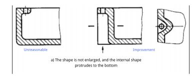
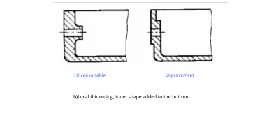
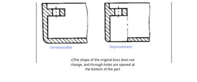
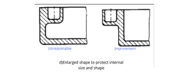
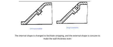
(1) Eliminate internal concave
(2) Avoid or reduce the core-pulling part
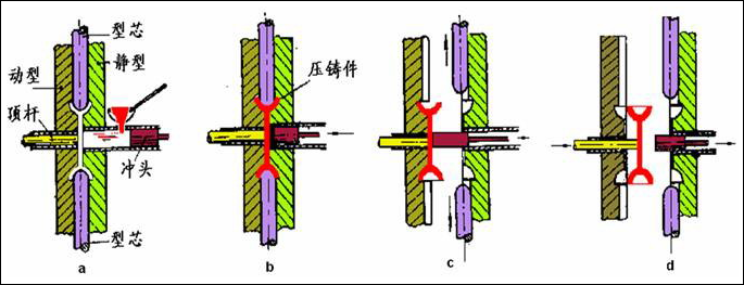
Die-casting core-pulling process
Methods to avoid and reduce core-pulling: ① non-important parts are completed by the subsequent process after the completion of die casting; ② Improve the structural design to meet the function at the expense of appearance. Such as:
(3)Avoid core crossing
2, Casting design wall thickness requirements
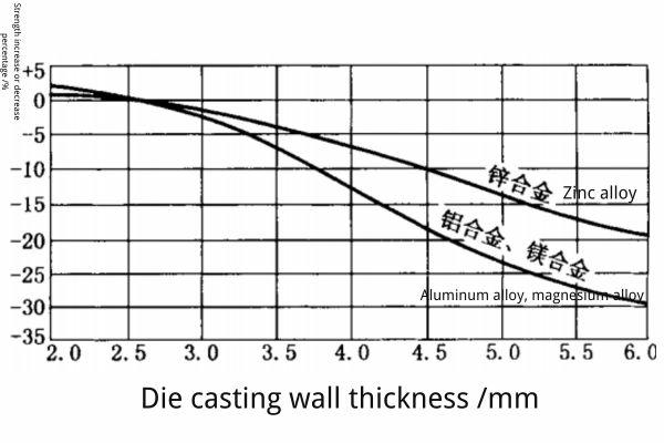
One of the characteristics of die casting design is the wall thickness design. Reasonable wall thickness depends on the specific structure of the casting, alloy properties and die casting technology and other factors. To meet the requirements of all aspects, normal and uniform wall thickness is preferred. The density of thin-walled castings is good, and the strength and pressure resistance of castings are relatively improved. But the wall can not be too thin, too thin alloy welding is not good, easily produces defects, and brings difficulties to the process, especially the large area of thin wall molding more difficult. The thickness or severe non-uniformity of the wall thickness is easy to produces shrinkage holes, porosity and other defects, so the mechanical properties of die casting parts are significantly reduced. The following figure shows the relationship between the strength of zinc alloy, aluminum alloy and magnesium alloy and the wall thickness of the casting.
|
Density and strength of aluminum alloy die castings with different wall thicknesses |
|||
|
Die casting wall thickness |
Dnsity | Die casting wall thickness | intensity |
| 2 | 2.86 | 2 | 270 |
| 5 | 2.78 | 3 | 210 |
| 7 | 2.74 | 6.5~8.0 |
175 |
Therefore, under the premise of ensuring that the casting has sufficient strength and stiffness, the thickness should be reduced as far as possible and the thickness of the section should be uniform. In order to avoid defects such as shrinkage and loosening, the thickness of the thick wall of the casting should be reduced and the reinforcement should be increased. The wall thickness of the die casting is generally 2 ~ 4mm, and the ratio of the maximum wall thickness to the minimum wall thickness in the same die casting is not greater than 3:1. Aluminum alloy parts with a wall thickness of more than 6mm should not be die-cast. The recommended minimum wall thickness and appropriate wall thickness are shown in Table 1. The larger the overall size of the die casting, the thicker the wall thickness should be. When the wall thickness is fixed, the area of the wall thickness should also be limited.
Minimum wall thickness and normal wall thickness of the die casting
|
Area at wall thickness a×b (cm2) |
Zinc alloy | Aluminum alloy | Magnesium alloy | Copper alloy | |||||
| 壁 厚 h (mm) | |||||||||
| minimum | normal | minimum | normal | minimum | normal | minimum | normal | ||
| ≤25 | 0.5 | 1.5 | 0.8 | 2.0 | 0.8 | 2.0 | 0.8 | 1.5 | |
| >25~100 | 1.0 | 1.8 | 1.2 | 2.5 | 1.2 | 2.5 | 1.5 | 2.0 | |
| >100~500 | 1.5 | 2.2 | 1.8 | 3.0 | 1.8 | 3.0 | 2.0 | 2.5 | |
| >500 | 2.0 | 2.5 | 2.5 | 4.0 | 2.5 | 4.0 | 2.5 | 3.0 | |
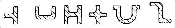
Die-casting parts of a variety of typical cross-section shapes
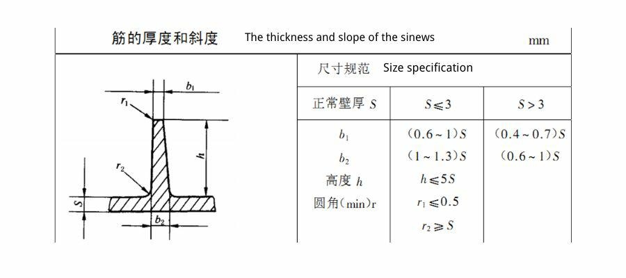
3, die casting design bar requirements
The function of the bar is to improve the strength and rigidity of the parts after the wall thickness is thinned, to prevent or reduce the shrinkage and deformation of the casting, to avoid the deformation of the workpiece when it is pushed out of the model, and to be used as an auxiliary loop (the path of metal flow) when it is filled. The thickness of the bar should be less than the thickness of the wall, and generally take 2/3 to 3/4 of the thickness of the wall. Table 3-1-4 shows section dimensions of ribs.
The setting principle of tendon: first, try to be symmetrical; Second, try to avoid reinforcement and cross between reinforcement and reinforcement in the same part, and try to avoid the layout of reinforcement can be dense; Third, the layout scheme of reinforcement should consider avoiding the situation of parts package fixed mold; The fourth is to consider the installation of anti-deformation tendons.
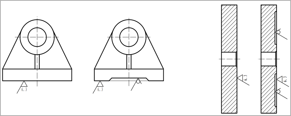
4 ,Die casting design requirements for rounded corners
Each part of the die casting should have rounded corners at the intersections (excluding the parting surface), so that the metal flow is smooth when filled, the gas can be easily discharged, and cracks caused by acute angles are avoided. Rounded corners on die castings that require plating and finishing help smooth out the coating and avoid paint accumulation at sharp edges. The rounded corner’s unreasonableness has a negative impact on the die’s strength, life, and stress concentration.
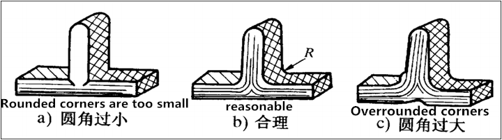
The rounded radius R of aluminum die casting is generally not less than 1mm, and the minimum rounded radius is 0.5mm.
| Die-casting alloy | Rounded radius R | Die-cast alloy | Rounded radius R | |
| zinc alloy | 0.5 | Aluminum and magnesium alloy | 1.0 | |
| aluminum-tin | 0.5 | Copper alloy | 1.5 |
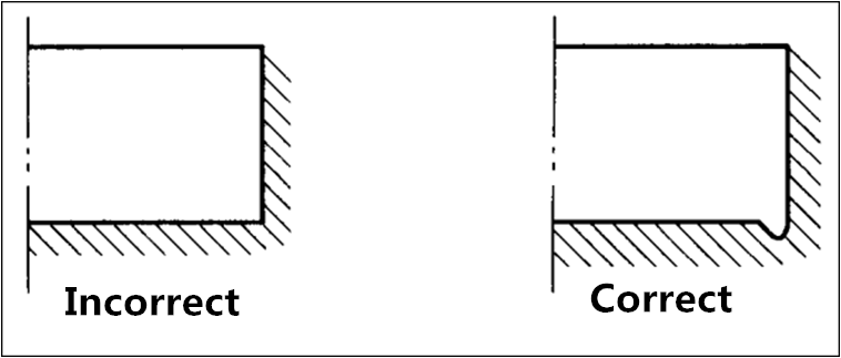
The sharp corners, right angles, blind holes and the root convex parts of the grooves of the casting should have rounded corners. When the inner Angle of the casting must be clear, the design should be referred to the following figure. Sometimes, considering the convenience of the model cavity processing, the same part can also be selected with equal-sized rounded corners.
5, casting design of the casting slope requirements
When designing die casting parts, the structural slope should be left on the structure, and when there is no structural slope, there must be the process slope of stripping where needed. The direction of the slope must be consistent with the direction of the casting release.
The recommended release slope is shown in the table.
The relationship of various sizes to depth and release slope Consult the manual on die casting mold design.
Release slope
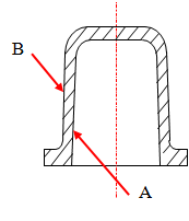 |
Alloy type | Minimum inclination of mating surface | Minimum slope of non-matching surface | ||
| Outer surface A | Inner surface B | Outer surface A | Inner surface B | ||
| Aluminum and magnesium alloy | 0˚15΄ | 0˚30΄ | 0˚30́ | 1˚ | |
| Zinc alloy | 0˚10΄ | 0˚15΄ | 0˚15΄ | 0˚45΄ | |
The dimensional deviation induced by this slope in casting is not included in the tolerance value.
The table values only apply to cavity depths or core heights of 50mm, surface roughness in Ra0.1, big end and small end.
The smallest single-sided size variation is 0.03mm. When the depth or height exceeds 50mm, or the surface roughness exceeds Ra0.1, the demoulding slope can be raised correspondingly.
High melting point alloys are greater than low melting point alloys; • thick walls are greater than thin walls; and • medial is greater than lateral. In general, the outside is half the size of the inside.
Complex shapes outnumber simple shapes.
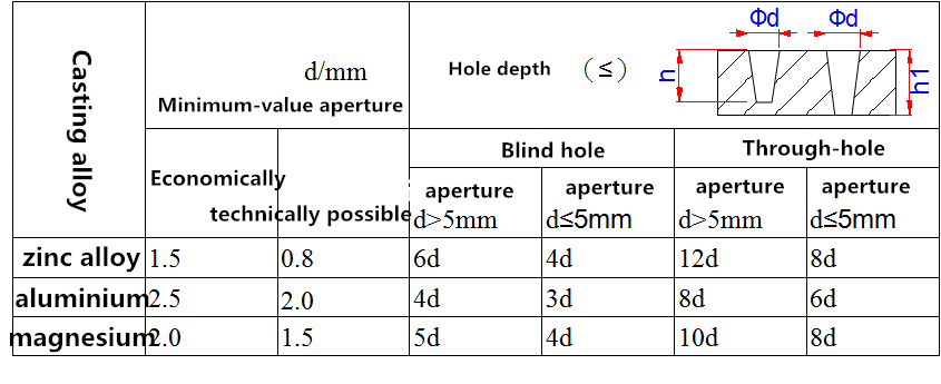
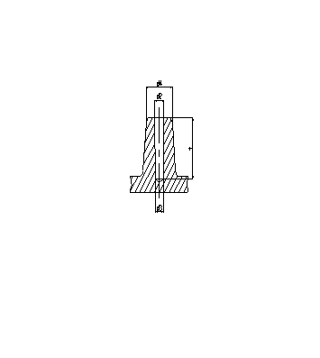
6, the minimum distance between the cast hole and the hole to the edge
1) Casting hole: the aperture and hole depth of the die casting, the hole with low requirements can be directly pressed out, and the following table can be pressed.
Because in actual production, the diameter of the needle below 2mm is very easy to deform and bend and break the needle, so
It is recommended that the shaped needle less than 2mm be directly made into a pilot needle, and the subsequent processing is guaranteed.
Recommended bottom hole diameter for self-tapping screws in die casting parts
 |
Thread specification d | M2.5 | M3 | M3.5 | M4 | M5 | M6 | M8 |
| d2 | 2.30~ 2.40 | 2.75~ 2.85 | 3.18~ 3.30 | 3.63~ 3.75 | 4.70~ 4.85 | 5.58~ 5.70 | 7.45
~ 7.60 |
|
| d3 | 2.20~ 2.30 | 2.60~ 2.70 | 3.08~ 3.20 | 3.48~ 3.60 | 4.38~ 4.50 | 5.38~ 5.50 | 7.15
~ 7.30 |
|
| d4 | ≥4.2 | ≥5.0 | ≥5.8 | ≥6.7 | ≥8.3 | ≥10 | ≥13.3 | |
| Screw in depth t | t≥1.5d | |||||||
bottom hole diameter for self-tapping screws (mm)
7, rectangular holes and slots on the die casting parts
Design recommendations for rectangular holes and slots on die castings, rectangular holes and slots
| Alloy | lead-tin alloy | Zinc alloy | Aluminium alloy | Magnesium alloy | Copper alloy |
| Minimum width b | 0.8 | 0.8 | 1.2 | 1.0 | 1.5 |
| Maximum depth H | ≈10 | ≈12 | ≈10 | ≈12 | ≈10 |
| Thickness h | ≈10 | ≈12 | ≈10 | ≈12 | ≈8 |
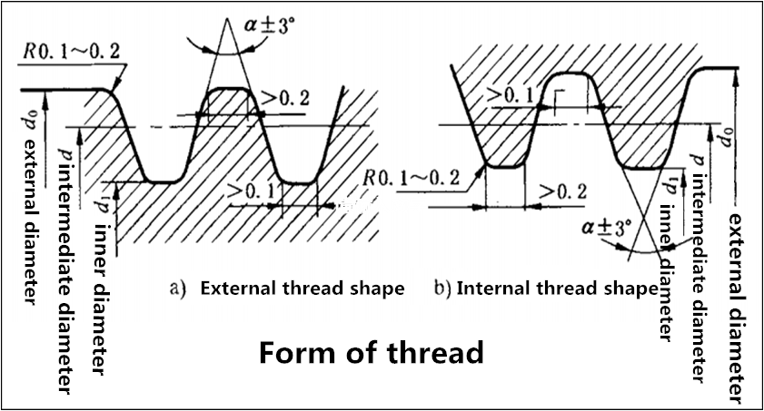
8, Casting design of die casting thread and gear
Under certain process conditions, the die casting parts of zinc, aluminum and magnesium alloys can be directly pressed out of the thread. Copper alloys are only die-cast threads in rare cases. The die casting thread is generally 3-level precision specified by the national standard. Die cast threads are usually more external threads. If necessary, the internal thread can also be die-cast. The external thread is divided into two kinds, one is composed of two half-thread cavities that can be separated, which is characterized by easy to produce wrong buckle, and the roundness is slightly worse, but it can reach the accuracy range, and it should be simply trimmed before use. The other is composed of a threaded ring, which is characterized by no wrong buckle, and good roundness, but low production efficiency and unsafe operation. The internal thread method is composed of the thread core, which is characterized by the thread core thread in the axis direction to have a slope, usually 10 ‘~15’, the thread length is limited. Die casting thread shape, should be flat or round head.
Flat head thread
9, die casting design convex, convex, and text and pattern
10 ,Casting insert in die casting design
Die cast parts can be cast into metal or non-metal inserts. The materials cast into the insert are mostly copper, steel, pure iron and so on. The role of the casting has such several aspects. ① Strengthen the strength, wear resistance, electrical conductivity and insulation of some parts of the die casting, such as casting steel in aluminum to improve strength, casting sapphire to improve wear resistance, casting insulation material to reduce cost and improve insulation, casting iron core to give magnetic conductivity. ② Remove the cavity of the die casting part that is too complex and the cavity that the inner concave can not be die-cast. ③ Eliminate hot knot, avoid loose. ④ The use of low-melting metal die-casting instead of precious metals, such as high-silicon aluminum instead of bronze. ⑤ Many small castings can be cast together instead of partial assembly.
Considerations for designing die castings with inserts:
① After casting, the casting is tightly wrapped by the base metal and should not be loosened;
② The base metal of the casting around the insert should not be less than 1.5 ~ 2mm, and the thickness of the large casting should be increased;
(3) There should be no electrochemical corrosion between the insert and the metal matrix of the casting, at this time, the surface of the insert can be added a protective layer;
④ The part surrounding the insert should not be a clear Angle and edge to avoid cracking the casting;
⑤ Castings with inserts should avoid heat treatment, to avoid different volume changes due to different phase transitions of the two metals, resulting in inserts loosening in the casting;
The insert should be able to meet the requirements of positioning and various tolerances in the model;
The shape and position of the insert on the casting should make it easy to place during die casting production.
The insert should not be too far away from the gate, so as not to weld fast, if it must be far away, the pouring temperature should be appropriately increased.
⑨ The inlays should be cleaned and cleaned, such as oil, ash, rust, etc., and should be preheated;
⑩ With threaded inserts, leave 1.5~2mm on the outside after embedding. When the inlay is pressed straight, mesh and other patterns, the width of the groove should not be less than 2mm and the depth should not be less than 1.5mm.
| Preheating temperature of metal inserts | |
| Die-casting allo | preheating temperature |
| Lead alloy, tin alloy | 60-80 |
| zinc alloy | 150-200 |
| Aluminum alloy, magnesium alloy | 200-250 |
| copper alloy | 250-350 |
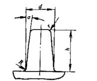
11,Design of rivet head
When the die casting is riveted with other parts, the rivet head can be cast at the same time as the casting in the die casting.
| Rivet head size | |||
 |
Dimension | Alloy | |
| Aluminium alloy | Zinc-Tin | ||
| Minimum diameter d | 1.5 | 1.0 | |
| Rounding radius R | 0.25 | 0.2 | |
| Inside radius r | 0.3 | 0.2 | |
| Maximum height h | 6d | 8d | |
| Minimum exit slope a | 1° | 15° | |
12, die casting parts to minimize the processing area
13, the processing allowance of die casting parts
When the dimensional accuracy or shape and position tolerance of the die casting fails to meet the requirements of the product drawings, finishing processing methods, such as correction, drawing, extrusion, shaping, etc., should be considered first. When machining is necessary, a small machining allowance should be considered, and the surface that is not affected by parting surface and active forming should be used as the blank base surface as far as possible.
Recommended machining allowance and deviation (mm)
| Basic size | ≤100 | >100~250 | > 250 ~400 | > 400 ~630 | > 630 ~1000 | |||||
| Margin on each side | 0.5 | +0.4
-0.1 |
0.75 | +0.5
-0.2 |
1.0 | +0.5
-0.3 |
1.5 | +0.6
-0.4 |
2.0 | +1
-0.4 |
Recommended reaming allowance (mm)
| Nominal aperture D | ≤6 | >6~10 | > 10 ~18 | >18 ~30 | >30 ~50 | >50 ~60 |
| Ream allowance | 0.05 | 0.1 | 0.15 | 0.2 | 0.25 | 0.3 |
14,Shrinkage rate of die casting parts
The shrinkage rate of die-casting parts includes the liquid shrinkage, solidification shrinkage, solid shrinkage of die-casting alloy and the influence of expansion when the working temperature of die-casting die rises. The main factors affecting the shrinkage rate are:
1) The more complex the casting structure, the more the number of cores, the more factors that hinder shrinkage, so the shrinkage rate is small.
2) Thin-wall castings shrink, and the shrinkage rate of wall thickness castings is large.
3) The radial dimension shrinkage of the enveloping core is blocked and the shrinkage rate is small.
4) When the casting temperature is high, the shrinkage rate is large, and the shrinkage rate is small.
5) The shrinkage of castings with inlays becomes smaller.
6) The residence time of the casting in the die casting mold is short, the demoulding temperature is high, the solid free shrinkage of the casting is large, in short, the contraction is larger, and the contraction is smaller.
Combining the above factors, it is difficult to accurately determine the shrinkage rate, and when calculating the molding size, the influence of the above factors is often integrated and the shrinkage rate is considered comprehensively. Actual experience data:
Depending on the wall thickness, the shrinkage rate of the wall thickness is high
Zinc alloy: K= (0.4%-0.8%) generally optional 0.6%
Aluminum alloy: K= (0.3%-0.7%) generally optional 0.5%
15,Epidermis
The outer surface of the cast part has a dense chill skin layer, which has higher mechanical properties than other parts of the casting. Therefore, designers should avoid mechanical processing to remove the dense layer of castings, especially for castings requiring wear resistance.
Quality requirements for aluminum alloy die casting parts
The quality requirements of aluminum alloy die casting parts are stipulated in the national standard GB/T 15114, the steam standard QC/T 273, and the navigation standard HB 963, and the domestic large companies also have their own enterprise standards.
The quality requirements of aluminum alloy die casting mainly include the following aspects:
1, chemical composition: should meet the national standard.
2, mechanical properties: The test of die-casting samples should meet the requirements of the national standard.
3, casting size: should comply with the requirements of the drawing, dimensional tolerance, shape and position tolerance, processing allowance, casting slope should comply with the relevant provisions.
4, the surface quality of the casting:
1) The surface roughness of the die casting should meet the requirements of GB/T6060.1.
2) The surface of the die casting is not allowed to have cracks, under-casting, porosity, bubbles and any penetrating defects.
3) The surface of the die casting is allowed to have defects such as scratches, depressions, lack of meat and mesh burrs. However, the defects must comply with the requirements in Table 1.
4) The gate, flash edge, overflow mouth, partition, top bar marks, etc. of the die casting should be cleaned. But you’re allowed to leave traces.
5) If the drawing is not specifically specified, the setting of the die casting process, such as the position of the ejector rod, the position of the parting line, the position of the gate and the overflow port, shall be specified by the manufacturer.
| Die casting surface quality requirements | |||
| Defect name | Defect range | Numerical value | Remark |
| graze | Depth mm | ≤0.10 | |
| The area does not exceed a percentage of the total area | 5 | ||
| hollow | Concave depth (mm) | ≤0.30 | |
| meat-poor | Depth( mm) | ≤0.50 | |
| The length is not greater than (mm) | 2 | ||
| The number that cannot be exceeded on the interface(mm) | 2 | ||
| Distance from die casting edge(mm) | ≥4 | ||
| Pitch (mm) | ≥10 | ||
| Reticular burr | Height (mm) | ≤0.2 | |
5, die casting machining surface quality after processing
1) Do not allow the presence of local as-cast skins that affect use.
2) No holes exceeding those specified in Table 2 are allowed.
| Holes allowed in the machined surface of die casting parts | ||||
| Maximum diameter(mm) | Maximum depth(mm) | Maximum number(mm) | Minimum distance between edges(mm) | |
| Hole | 1.0 | 1.0 | 2 | 4 |
6, die casting machining thread surface quality
1) The first two buttons of the machined thread of the die casting are not allowed to have any defects, and the remaining parts of the thread are not allowed to have the hole defects specified in Table 3.
2) Die casting does not cast the surface quality of the thread after the bottom hole processing
|
Machined thread specified hole defect range |
||||
| Screw pitch(mm) | Mean diameter(mm)≤ | Number of working lengths of thread≤ | Depth(mm) ≤ | The margin between the two holes(mm)≥ |
| ≤0.75 | 1 | 1 | 2 | 2 |
| >0.75 | 1.5 | 4 | 1.5 | 5 |
|
Surface quality of thread after bottom hole machining without die casting |
||
| Screw pitch(mm) | Minimum distance between hole and end face (mm) | Hole length does not exceed a percentage of the effective thread length |
| ≤0.75 | 3 | 20 % |
| >0.75 | 5 | 25% |
7.The specified range of holes on the surface of die-casting parts after machining holes 1) When the diameter of the machined hole is Æ≤11 mm and L > 50 mm, no holes are allowed on the surface with a length of 10mm at both ends of the hole.2) When the diameter of the machining hole is Æ> 11mm and L > 30mm, no holes are allowed on the surface with a length of 6mm at both ends of the hole.
| The specified range of holes on the surface of die-casting parts after machining holes | ||||
| Machining hole diameter(mm) | Hole length(mm) | Mean hole diameter(mm) | Cavity depth(mm) | Number of holes |
| Φ≤11 | L≤50 | ≤1.5 | ≤1.0 | ≤2 |
| L>50 | ≤2.0 | ≤1.5 | ≤3 | |
| Φ>11 | L≤30 | ≤1.5 | ≤1.0 | ≤2 |
| L>30 | ≤2.0 | ≤1.5 | ≤3 | |
8.Internal quality of die casting parts
1) If the die casting can meet its performance requirements, the essential defects of the die casting are not used as the basis for scrapping.
2) No cold insulation defects are allowed inside the die casting parts.
3) Defects such as pores, holes and inclusions are allowed inside the die-casting parts, but the maximum diameter of the hole defects does not exceed 1/8 of the wall thickness, and the number of holes does not exceed 2 /cm2 on any section.
4) The stress parts of important die castings must be dissected
|
Die casting internal quality specification for specified anatomical parts |
|||
| Mean hole diameter(mm) | Maximum number c㎡ | Minimum distance between edges (mm) | |
| hole | Φ≤0.5 | ≤1 | 4 |
JH MIM, which started as MIM, has established a sound product ecology by investing in advantageous enterprises in related industries. Now it can provide customers with one-stop services such as Powder Metallurgy Process, Die Casting, CNC, and 3D printing. It is equipped with integrated assembly capabilities and the quality of quality suppliers mentioned above. Please click the link below for more detailed information.