
Custom MIM Synchronizer Rings | High-Strength OEM Gearbox Components
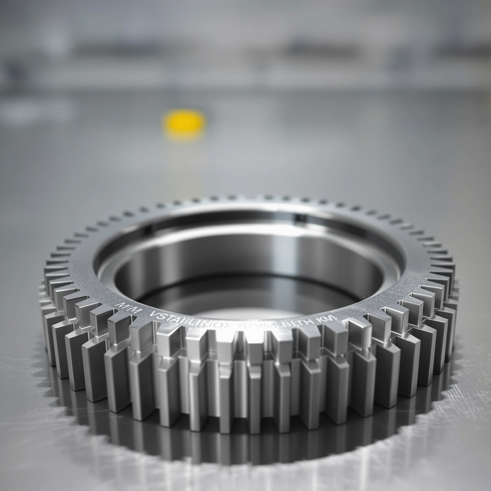
Manual transmission systems rely on synchronizer rings to equalize rotational speeds between gears during shifting operations. These metal components act as friction interfaces that enable smooth, clash-free gear engagement by matching shaft speeds before the selector sleeve locks into position. Metal injection molding has emerged as a state-of-the-art production method for manufacturing these critical transmission components, producing complex-shaped metal parts with consistent quality, exceptional wear resistance, and high dimensional accuracy.
Synchronizer rings are classified into several configurations based on friction surface design. Single-cone synchronizer rings feature one conical friction surface. Double-cone and triple-cone systems multiply the friction area without increasing the component’s overall diameter. Multiple-cone systems are deployed in low gears where speed differences during synchronization create greater demands on friction forces for accelerating and braking gearwheels. This multi-cone approach provides higher torque capacity and significantly reduced shift times compared to single-cone designs.
The manufacturing of synchronizer rings employs various processes including forming, sintering, and forging. Metal injection molding utilizes fine metal powders custom-compounded with a binder into feedstock, which is injected into precision mold cavities, then undergoes debinding and vacuum sintering to achieve maximum density. MIM produces parts with mechanical properties comparable to wrought components made through conventional metalworking methods. The process delivers virtually unlimited shape and geometric-feature capabilities, high production rates, and minimal material loss.
Material selection spans multiple alloy systems. Steel-based synchronizers with specialized heat treatments offer high mechanical strength and smaller tooth modules. Carbon composite friction materials provide improved frictional characteristics and constant friction levels. Traditional brass synchronizer rings manufactured through hot forging remain common for specific applications requiring particular friction coefficients. However, steel synchronizers manufactured via MIM with carbon linings or molybdenum coatings deliver unmatched durability and energy absorption for heavy-duty automotive and industrial applications.
MIM technology produces net-shape components with typical densities reaching 96 to 99 percent of wrought material. This high density ensures mechanical properties equal to wrought steel while maintaining excellent surface finish in the as-sintered condition, minimizing the need for secondary finishing operations.
What Are MIM Synchronizer Rings?
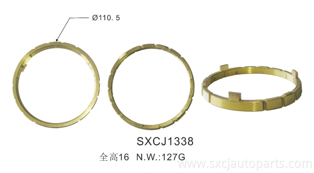
Role of Synchronizer Rings in Manual Transmissions
Speed differentials between rotating shafts create the fundamental challenge that synchronizer rings solve. The transmission must connect components spinning at different speeds without grinding or clashing when shifting gears. The synchronizer ring functions as a friction clutch that accelerates or decelerates the input shaft to match the output shaft speed before full gear engagement occurs.
The synchronization process unfolds in distinct phases. The shift fork moves the sliding sleeve toward the target speed gear when the driver selects a gear. Keys or struts push the blocking ring against the cone surface of the gear wheel and generate friction torque. This friction force equalizes rotational speeds between the shaft-mounted synchronizer assembly and the freewheeling speed gear. The blocking ring prevents the sleeve from engaging gear teeth until synchronization completes. The friction relaxes and the ring’s external teeth line up with the sliding sleeve once speeds match, permitting full engagement of the speed gear’s clutch teeth.
MIM vs. Traditional Machining & Forging Methods
Metal injection molding offers distinct advantages over conventional manufacturing approaches for synchronizer ring production. MIM routinely achieves tight dimensional tolerances of ±0.01 mm to ±0.05 mm, whereas traditional drop-forging typically delivers ±0.5 mm tolerance. This extreme precision eliminates expensive secondary machining operations for complex tooth profiles and oil grooves.
Material efficiency also sets MIM apart. Conventional CNC machining removes substantial material as scrap, increasing raw material costs. MIM recycles excess feedstock and utilizes up to 98% of the raw material. MIM becomes exceptionally cost-effective for complex geometries because mold investments remain constant regardless of feature intricacy, whereas machined parts accumulate labor and tooling costs with each additional feature.
Powder metallurgy synchronizer hubs and rings have captured a dominant market share in transmission components driven by superior price-to-performance ratios. MIM parts reach nearly 90% to 98% of wrought forging strength while offering net-shape capabilities that traditional forging cannot match without extensive machining.
Main Components of a Synchronizer Ring Assembly
A complete synchronizer system integrates five primary elements working in harmony:
- Synchronizer hub: Splined directly to the transmission shaft, rotating with it and housing the sliding keys/locking elements.
- Sliding sleeve: Moves axially to transfer torque from the shaft-hub assembly to the clutch gear.
- Synchronizer ring (Blocking Ring): Provides the critical friction surface that matches speeds before gear engagement.
- Clutch gear with friction cone: Mates with the synchronizer ring during the speed equalization phase.
- Transmission gear: Freewheeling component that locks to the input shaft once full sleeve engagement is achieved.
The synchronizer ring itself features internal threads or specialized micro-groove patterns designed to cut through lubricant films on the cone surface, preventing hydrodynamic floating and ensuring rapid synchronization times.
Metal Injection Molding Process for Synchronizer Rings
High-Density Metal Powder Selection & Feedstock Preparation
Feedstock preparation combines ultra-fine metal powders (typically 2–20 µm particle size) with a multi-component thermoplastic binder system. Powder loading ranges from 50 to 65 vol%, equivalent to 88–93 wt% for steel alloy synchronizer rings. The binder system typically consists of backbone polymers such as polypropylene or high-density polyethylene (35 wt%) and waxes including paraffin or carnauba wax (62 wt%), along with specialized surfactants like stearic acid (3 wt%).
The mixture is heated to temperatures between 120°C and 180°C depending on binder formulation. Shear rates during high-shear dispersive mixing reach 50–200 s⁻¹. Twin-screw extruders ensure homogeneous feedstock blending with precise temperature control under an inert gas (nitrogen or argon) atmosphere to prevent oxidation of reactive metal alloys.
Precision Injection Molding & Debinding Stages
Once granulated into uniform pellets, the feedstock undergoes injection molding using specialized plastic injection molding machinery. The material melts in the heated barrel and is injected under high pressure into precision-engineered mold cavities, producing “green parts” that are scaled approximately 15% to 20% larger to account for shrinkage during sintering.
Debinding removes the organic binder through a controlled two-stage process. Solvent debinding at 50–70°C extracts waxes and primary soluble components over 6 to 23 hours. Thermal debinding then eliminates the residual polymer backbone at temperatures reaching 500°C with gradual heating rates (0.5–1°C/min) to prevent internal cracking or structural distortion.
Vacuum Sintering Temperature and Density Control
Vacuum sintering densifies the fragile “brown parts” into high-strength metallic components. Sintering temperatures approach 85% of the alloy’s melting point—typically between 1,120°C and 1,350°C for high-strength steel alloys. Controlled vacuum or reduced-pressure hydrogen/argon atmospheres protect the parts from oxidation and ensure effective carbon control. Final sintered density routinely reaches 95% to 99% of theoretical density.
Secondary Operations & Surface Finishing
While MIM achieves net-shape precision, high-stress automotive synchronizer rings often undergo minimal secondary processing to satisfy extreme performance requirements. These operations include precision sizing or coining for ultra-tight tolerances, thermal heat treatments (such as carburizing, carbonitriding, or induction hardening) to boost surface hardness, and advanced friction coating application (molybdenum spraying or carbon lining integration).
Material Properties and Performance Advantages
High-Strength Steel Alloys for MIM Synchronizer Rings
Material engineering is key to achieving long service life under extreme shifting loads. MIM synchronizer rings frequently utilize low-alloy sintered steels (such as Fe-Ni-Mo and Fe-Cu-C systems) or precipitation-hardening stainless steels (like 17-4PH). Alloy formulations featuring nickel, molybdenum, and chromium deliver excellent hardenability, allowing core tensile strengths exceeding 850–1,100 MPa after heat treatment, while maintaining sufficient ductility to withstand heavy impact torque during high-RPM gear shifts.
Friction Cone Surface Requirements & Friction Coefficient
The inner or outer conical surface of the synchronizer ring must exhibit a stable friction coefficient ($\mu$) across varied operating oil temperatures and sliding velocities. Standard MIM synchronizer surfaces are designed to maintain dynamic friction coefficients in the range of 0.08 to 0.12 against mating steel cones. Fine surface texturing, oil distribution grooves, and micro-threading are directly molded into the MIM part, effectively dispersing transmission fluid films to facilitate immediate mechanical contact during engagement.
Wear Resistance, Tensile Strength & Fatigue Life
Transmission synchronizer rings experience severe rolling-sliding friction and repetitive contact fatigue. MIM steel synchronizers exhibit superior fatigue limits due to their fine, isotropic grain structure and near-full theoretical density. Case hardening treatments elevate surface hardness to 58–62 HRC, conferring exceptional resistance to adhesive wear, pitting, and spalling under heavy automotive torque demands.
Dimensional Accuracy and Complex Tooth/Spline Geometries
One of the primary advantages of MIM technology lies in its ability to mold complex locking teeth, pointing angles, roof angles, and internal splines directly into the net shape without requiring multi-axis CNC milling. MIM consistently achieves dimensional tolerances of ±0.3% to ±0.5% nominal dimensions, with critical feature tolerances held to ±0.01 mm through secondary sizing. This capability guarantees smooth sliding action and precise angular alignment with the sliding sleeve.
Types of MIM Synchronizer Ring Configurations
Image Source: Facebook

Single-Cone Synchronizer Rings
Single-cone configurations utilize a single conical friction surface between the blocking ring and the gear cone. Representing the most compact synchronizer design, they are primarily deployed in higher gear ratios (such as 3rd through 6th gears) where speed differentials between shifts are lower. MIM single-cone rings provide lightweight, cost-effective performance while offering highly repeatable tooth geometry that ensures consistent shift feel.
Double-Cone and Triple-Cone Configurations
Lower transmission gears (1st, 2nd, and Reverse) require significantly higher synchronization torque due to substantial speed differentials. Double-cone and triple-cone configurations solve this challenge by incorporating intermediate rings and multiple friction surfaces, effectively doubling or tripling the total friction contact area within the same radial envelope. MIM excels at producing these multi-cone components—including intermediate rings with molded driving lugs and complex oil-channel grooves—at a fraction of the cost of forged equivalents.
Friction Material Integration Options (Carbon/Brass Lined)
To withstand extreme thermal energy absorption during high-load shifting, modern MIM synchronizer rings are engineered to integrate advanced friction linings. Carbon friction linings and carbon-composite paper materials offer superior dynamic stability and thermal durability under severe pressure compared to traditional brass linings. The high surface density and dimensional accuracy of MIM steel substrate rings provide a clean, rigid backing for thermal bonding of carbon friction linings.
Custom Tooth Profiles & Internal/External Spline Geometries
Gear shift feel depends heavily on the geometry of the blocking teeth and spline flanks. Involute splines molded via MIM offer self-centering characteristics and optimal load distribution across all spline teeth. Furthermore, MIM technology easily incorporates complex locking features—such as back-tapered teeth or inverted roof angles—that prevent gear pop-out under heavy engine load.
OEM Production Capabilities, Tooling & Lead Times
Rapid Prototyping (Binder Jet / Soft Tooling) to Mass Production
Development timelines for custom synchronizer rings require flexibility during early engineering phases. JHMIM offers binder jetting 3D printing to produce fully functional metal prototype parts without hard tooling investment, enabling rapid testing of tooth designs and friction fitments. For low-volume validation, aluminum soft tooling offers an intermediate solution. High-volume mass production utilizes multi-cavity hardened tool steel molds capable of producing millions of parts with zero dimensional drift.
Minimum Order Quantities (MOQ) and Delivery Lead Times
The economic benefits of metal injection molding become evident in medium- to high-volume production. Hardened steel tooling production typically requires 6 to 10 weeks, followed by sample submission and PPAP (Production Part Approval Process) validation. Standard production lead times for batch orders are 3 to 5 weeks. MIM is ideally suited for annual production quantities ranging from 5,000 to over 1,000,000 units per year.
Cost Analysis: MIM Tooling Investment vs. CNC Piece-Part Savings
Although precision MIM tooling requires an upfront capital investment, multi-cavity molds amortize this expense rapidly across production runs. Compared to traditional CNC machining—where each complex undercut, thread, and gear tooth incurs linear machine hour costs—MIM mold cycle times produce net-shape components every few seconds. On complex synchronizer rings, MIM reduces piece-part unit costs by 30% to 60% compared to full CNC machining.
Quality Control, Testing Standards & Automotive Certifications
Density Measurement (Archimedes Method) & Porosity Analysis
Density directly correlates with mechanical strength and fatigue resistance in powder metallurgy parts. Hydrostatic density measurement according to Archimedes’ principle provides real-time verification during production. Metallographic cross-sectioning and image analysis inspect pore size distribution, ensuring closed porosity structures and sintered densities exceeding 96% to 98% throughout critical stress areas.
Friction Coefficient and Wear Testing Methods
JHMIM subjects custom synchronizer rings to rigorous tribological testing. Ring-on-cone friction test rigs simulate thousands of engagement cycles under controlled axial loads, shifting speeds, and oil temperatures. Automated sensors continuously measure dynamic friction coefficients, drag torque, wear rates, and thermal dissipation performance under severe shift cycles.
High-Torque Load Capacity & Endurance Testing
Structural integrity testing ensures every synchronizer ring design withstands peak shock torque without tooth shear or deformation. Torsional destruction testing and dynamic bench endurance runs evaluate fatigue performance under over-torque shifting conditions, guaranteeing long-term reliability in OEM automotive and industrial transmissions.
IATF 16949 & ISO 9001 Automotive Certification Requirements
Automotive drivetrain component manufacturing demands strict quality management systems. JHMIM operates under certified ISO 9001 and IATF 16949 quality management protocols. Rigorous Quality Assurance procedures—including full APQP development, FMEA risk assessment, MSA measurement analysis, and complete PPAP Level 3 documentation—ensure full compliance with Tier-1 and OEM automotive procurement standards.
Partner with JHMIM for Custom Synchronizer Ring Manufacturing
Request a Fast DFM Analysis & Instant Quote Today
JHMIM’s engineering team provides comprehensive Design for Manufacturability (DFM) evaluations for custom automotive drivetrain components. By submitting your 3D CAD files (STEP, IGES, Parasolid, or SolidWorks) along with 2D engineering drawings, our engineering team evaluates draft angles, wall uniformity, tooth geometry, and sintering shrink factors to optimize part performance and reduce tooling costs.
Whether you require custom single-cone rings for high-performance gearboxes or multi-cone assemblies for heavy-duty commercial vehicle transmissions, JHMIM delivers high-precision, high-strength MIM components tailored to your exact specifications. Contact our engineering support team today to receive a detailed DFM analysis and competitive OEM quotation.
Conclusion
Metal injection molding has revolutionized synchronizer ring manufacturing by delivering high-density, high-strength components with complex net-shape geometries at unmatched cost efficiencies. By combining the material performance of wrought steel alloys with the design freedom of injection molding, MIM eliminates costly CNC machining operations while holding tight dimensional tolerances. Whether deployed in single-cone or complex multi-cone transmission systems, MIM synchronizer rings provide the durability, wear resistance, and precise shift performance required by global automotive OEMs. Partner with JHMIM to streamline your transmission component manufacturing with world-class MIM engineering expertise.
A synchronizer ring acts as a friction clutch interface that matches the rotational speeds of the input shaft and target speed gear prior to mechanical engagement. This prevents gear teeth grinding, ensuring smooth, clash-free gear changes in manual and dual-clutch transmissions.
MIM provides near-net shape capability with dimensional tolerances as tight as ±0.01 mm, eliminating extensive secondary CNC machining required for forged blanks. Furthermore, MIM reduces material waste by recycling feedstock, cutting unit component costs by 30% to 60% while achieving up to 98% of forged steel strength.
MIM synchronizer rings achieve sintered densities between 95% and 99% of theoretical density (typically 7.5 to 7.8 g/cm³ for steel alloys). This near-full density provides mechanical strength, fatigue life, and wear resistance equivalent to conventional wrought steel alloys.
MIM synchronizer rings primarily utilize heat-treatable low-alloy steels (such as Fe-Ni-Mo and Fe-Cu-C systems) or precipitation-hardening stainless steels (like 17-4PH). These materials deliver tensile strengths exceeding 850–1,100 MPa after heat treatment, satisfying demanding automotive transmission requirements.
JHMIM operates under ISO 9001 and IATF 16949 automotive quality certification management systems, providing complete PPAP documentation, APQP planning, and full lot traceability required by OEM automotive and industrial transmission manufacturers worldwide.