
Key Takeaways
- Focus on the Root Fillet: High-torque pinion tooth shear and fatigue failures rarely start at the pitch line; they predominantly initiate near the 30-degree tangent point of the root trochoid.
- Substantial Stress Reduction: Transitioning from a standard profile to a full-radius root cutter (increasing cutter tip coefficient from 0.25 to 0.38-0.40 mn) reduces the stress concentration factor (Kf) by 15% to 20%.
- Weight & Mass Efficiency: Optimizing the root radius delivers strength gains comparable to increasing the gear module, but with less than a 1% mass penalty (versus a 20%-30% volume increase from a larger module).
- Design for Transient Spikes: Root radii must be calculated for peak shock loads and emergency stops, not just nominal operating torque.
- Strict Tool Management Required: Cutter tip wear of just 0.15 mm can sharpen the resulting fillet, inadvertently raising localized root stress by 12% to 15%.
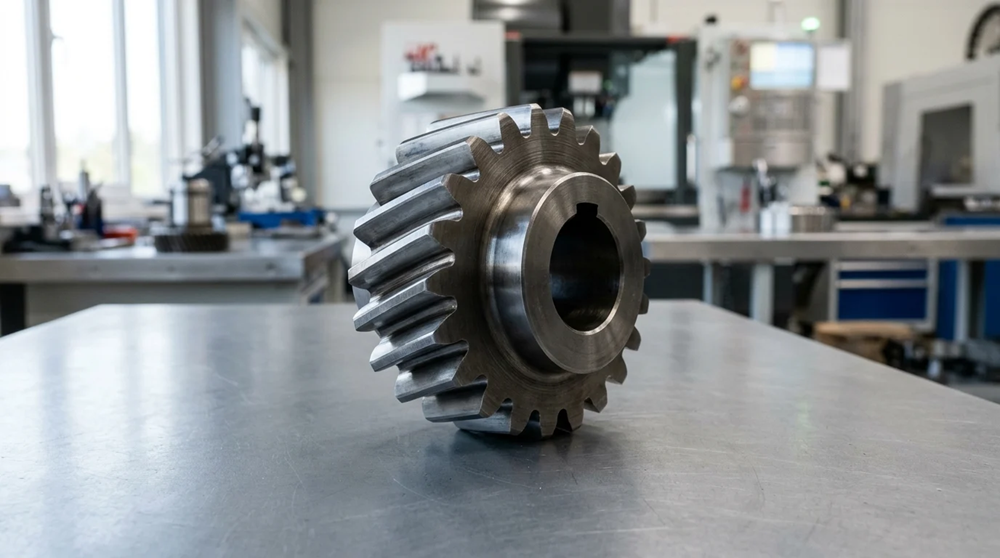
A pinion tooth rarely fails because the entire gear is weak; it often fails because stress is concentrated in a few millimeters at the root. In high-torque drives, that small fillet can determine whether the tooth survives millions of cycles or shears under a shock load. This guide examines how root radius, trochoid geometry, cutter tip selection, and fatigue stress concentration influence bending strength. It also explains why cracks commonly initiate near the root fillet, how peak torque events accelerate damage, and why optimizing the fillet can deliver measurable strength gains without redesigning the whole gear.
Why Tooth Root Radius Matters
High-torque pinions in heavy industrial, automotive, and aerospace applications face extreme demands, making gear tooth bending strength a paramount engineering concern. Among the most critical yet frequently under-optimized geometric features is the tooth root radius. Proper management of the root fillet geometry directly dictates the stress concentration factor, serving as the primary defense against catastrophic tooth shearing and bending fatigue failures.
How Root Fillets Reduce Stress Concentration
When a gear tooth transmits torque, it acts as a cantilever beam. The bending moment reaches its maximum at the base of the tooth, where the profile transitions into the root circle. The root fillet distributes these bending stresses over a larger surface area. By optimizing the root radius, engineers can reduce the theoretical stress concentration factor (Kt) by 15% to 20%. This significantly elevates the pinion’s load-carrying capacity without altering its overall pitch diameter or macro-geometry.
Where Tooth Shear Failures Usually Start
Tooth shear and bending fatigue failures rarely initiate at the pitch line; they predominantly start at the root fillet. Specifically, micro-cracks tend to nucleate near the 30-degree tangent point of the root trochoid curve. Depending on gear geometry and loading conditions, these cracks often begin at shallow subsurface depths. Once a crack initiates in this high-stress zone, continuous cyclical loading propagates it across the tooth base, eventually culminating in complete shear failure.
Why Fatigue Risk Increases Under Peak Torque
Peak torque events—such as system start-ups, emergency stops, or shock loads—dramatically escalate fatigue risk. During these transient events, applied torque can spike significantly above nominal operating levels. If the root radius is insufficiently sized to handle these spikes, localized stress rapidly exceeds the material’s yield strength. This induces localized plastic deformation and accelerates the fatigue crack initiation phase.
Key Design Parameters for Root Fillets
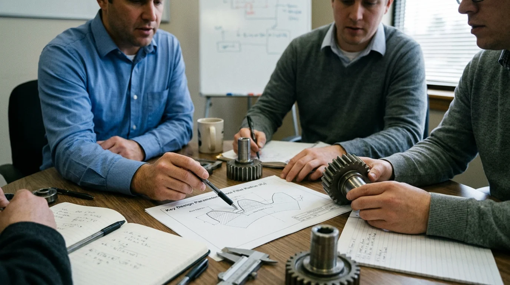
The precise contour of the root fillet is not an arbitrary curve; it is a complex trochoid generated by the tip of the cutting tool during manufacturing. Understanding and manipulating the parameters that define this geometry is essential for maximizing bending strength in high-torque pinions.
Root Radius, Trochoid Shape, and Fillet Geometry
Root fillet geometry is dictated by the cutter tip radius coefficient (ρa0) and the generating pitch line. In standard gear design, ρa0 is typically 0.25 to 0.30 times the normal module (mn). For high-torque applications, utilizing a full-radius cutter can push this coefficient to 0.38 or even 0.40. This maximizes the trochoidal radius and smooths the stress flow lines at the base of the tooth.
Stress Concentration Factor and Bending Fatigue Limit
The relationship between fillet geometry and bending fatigue is quantified by the fatigue stress concentration factor (Kf). A larger, smoother root radius reduces Kf, thereby increasing the pinion’s allowable bending fatigue limit. Note that the values in the table below are illustrative; actual Kf values and strength gains depend heavily on specific gear parameters, such as tooth count, pressure angle, and helix angle.
| Profile Type | Cutter Tip Radius (ρa0 / mn) | Stress Concentration Factor (Kf) | Bending Strength Increase |
|---|---|---|---|
| Standard Profile | 0.25 | 1.65 | Baseline |
| Modified Radius | 0.30 | 1.52 | +8.5% |
| Full-Radius Root | 0.38 | 1.41 | +17.0% |
Relevant AGMA and ISO Design Methods
International standards provide robust frameworks for evaluating root stresses. The AGMA 2001-D04 standard utilizes the geometry factor (J) to account for stress concentration and load sharing, while ISO 6336-3 relies on the form factor (YF) and the stress correction factor (YS). Both methodologies require precise inputs regarding the root fillet radius to accurately calculate root bending stress, ensure it remains below the material’s permissible fatigue limit, and verify required safety factors prior to engineering release.
Root Radius Compared With Other Strengthening Methods
While modifying the root radius is a highly effective method for mitigating stress concentration, it is not the only tool available to gear designers. Comparing root radius optimization against other strengthening strategies reveals important trade-offs regarding weight, spatial constraints, and tooling investment.
Increasing Root Radius vs. Increasing Gear Module
The most direct alternative to increasing the root radius is increasing the gear module, which thickens the entire tooth. However, increasing the module by just 1.0 mm can inflate the overall volume and mass of the gearset by 20% to 30%. In contrast, optimizing the root radius requires less than a 1% increase in mass while providing a comparable improvement in bending fatigue resistance. This makes it ideal for weight-sensitive gearboxes. Still, implementing a full-radius root often requires custom cutters and careful profile shift compensation, introducing unique tooling trade-offs compared to simply scaling up the module.
Larger Fillets vs. Contact Ratio and Clearance
Enlarging the root fillet introduces geometric constraints, particularly concerning mating gear tip clearance. A standard gear design maintains a bottom clearance (c) of 0.25 mn. Utilizing a larger root radius may reduce this clearance to 0.15 mn or less, risking tip interference with the mating gear. To resolve this, designers must balance contact ratio and clearance. Unlike a module increase—which scales all proportions equally—optimizing the fillet often requires positive profile shifts (addendum modification) or trimming the mating gear’s outside diameter to safely accommodate the larger radius.
When Material Upgrades or Heat Treatments Are Better
When geometric optimization reaches its physical limits or tooling costs for custom fillets become prohibitive, material and surface treatment upgrades become necessary alternatives. Processes like case carburizing or carbonitriding drastically increase surface hardness, while shot peening induces beneficial residual compressive stresses ranging from -400 MPa to -600 MPa in the root area. While a larger root radius passively lowers applied tensile stress by smoothing the geometry, shot peening actively counteracts it through residual stress enhancement. In ultra-high-torque scenarios, the most robust pinions combine full-radius roots with advanced surface treatments.
Need Expert Gear DFM & Root Geometry Evaluation?
Optimizing root fillet geometry and tooth stress distribution requires deep expertise in gear manufacturing and powder metallurgy/MIM tooling. Let JHMIM analyze your custom gear designs.
Contact JHMIM’s Engineering Team Today for a Free DFM Review & Quote →
Practical Steps to Reduce Stress Concentration
Translating theoretical root fillet optimizations into a physical, production-ready pinion requires a structured engineering workflow. This process demands rigorous load analysis, advanced simulation, and strict manufacturing controls.
Build Load Cases for Torque, Shock, and Duty Cycle
The first step is establishing comprehensive load cases. Engineers must define the Load Duration Distribution (LDD), which maps the frequency and magnitude of nominal torques, shock loads, and peak transients over the pinion’s design life (e.g., 107 or 108 cycles). Accurate load cases are critical; underestimating a peak shock load by even 15% can invalidate fatigue life calculations for the root radius.
Iterate the Root Radius Using FEA Simulation
Finite Element Analysis (FEA) is indispensable for iterating the root radius. Because stress gradients at the fillet are extremely steep, the FEA mesh density must be highly refined in this localized area. Best practices dictate an element size of ≤0.1 mm at the root, or a minimum of 5 to 7 elements spanning the radius arc, preventing artificial stress averaging and capturing true peak strains.
Control Manufacturing to Preserve Fillet Geometry
The optimized root geometry is only as good as the manufacturing process that creates it. Tool wear on hobs, shaping cutters, or compaction dies directly degrades the trochoidal root form. Cutter tip wear of just 0.15 mm can sharpen the resulting fillet, inadvertently causing localized root stress to increase by 12% to 15%. Implementing strict tool life management and post-machining CMM inspection is mandatory to preserve the designed fillet geometry.
Decision Criteria for Engineering Release
Releasing a high-torque pinion design to manufacturing requires a definitive set of decision criteria. Engineering teams must weigh theoretical fatigue improvements against practical production realities.
Set Acceptance Criteria for Fatigue and Safety Factor
Building on AGMA and ISO methodologies, engineers must establish a minimum safety factor for bending fatigue (SF). This is typically between 1.25 and 1.40 for industrial gearboxes, or up to 1.60 for mission-critical aerospace drives. The chosen root radius must demonstrably satisfy these safety factors across all defined load cases, including peak transient events.
Balance Cost, Manufacturability, and Supplier Capability
Optimizing the root often requires custom cutting tools or specialized sintering dies, which impacts project economics. Procuring a custom full-radius hob can increase initial tooling costs by 30% to 50% and extend lead times by 4 to 6 weeks compared to standard tooling. Engineering management must balance the required safety factor against supplier capabilities, ensuring the manufacturing partner possesses the precision machinery to hold tighter fillet tolerances.
Use a Final Release Checklist for Root Radius Approval
To ensure no critical parameters are overlooked during engineering release, teams should utilize a formalized validation checklist:
| Parameter | Minimum Threshold / Requirement | Validation Method |
|---|---|---|
| Bending Safety Factor (SF) | > 1.40 (Application dependent) | FEA & ISO 6336 Calculation |
| Tip Clearance (c) | > 0.15 mn | 2D/3D Kinematic Simulation |
| Residual Stress at Root | < -400 MPa (Compressive) | X-Ray Diffraction (First Article) |
| Cutter Tip Radius (ρa0) | Verified to drawing spec ±0.02 mm | CMM Optical Profiling |
Conclusion: Partner with JHMIM for High-Strength Precision Gear Solutions
Tooth root radius optimization offers one of the highest leverage opportunities in gear engineering—delivering up to a 20% reduction in stress concentration without adding structural weight or altering the gear module. By carefully managing the 30-degree trochoid tangent zone, selecting full-radius tooling, and controlling manufacturing wear, engineers can prevent premature bending fatigue and catastrophic tooth shearing under severe torque spikes.
At JHMIM, we combine advanced Powder Metallurgy (PM) and Metal Injection Molding (MIM) with precision gear tooling design. Whether you are developing high-torque spur gears, helical pinions, or complex cluster gears, our technical team ensures your root geometries, density profiles, and surface heat treatments meet strict fatigue standards.
Ready to enhance your gear set’s fatigue resistance? Contact JHMIM’s engineering team today or upload your 3D CAD files for a comprehensive DFM and stress optimization evaluation within 24 hours.
Frequently Asked Questions (FAQs)
Q1. Why is the tooth root radius critical in high-torque pinions?
The tooth root radius controls how bending stress flows through the base of the gear tooth. A larger, smoother fillet reduces the stress concentration factor, preventing micro-crack initiation, bending fatigue, and tooth shearing under load.
Q2. Where do gear tooth shear failures usually begin?
Most tooth shear failures initiate at the root fillet rather than the pitch line. Micro-cracks commonly form near the 30-degree tangent point of the root trochoid, where cyclic bending tensile stress reaches its maximum value.
Q3. How much can root fillet optimization reduce stress concentration?
Transitioning from a standard profile to an optimized full-radius root can reduce the fatigue stress concentration factor (Kf) by 15% to 20%, significantly raising allowable fatigue limits.
Q4. What cutter tip radius is typical for standard vs. high-torque gear design?
Standard gear designs typically use a cutter tip radius coefficient (ρa0) of 0.25 to 0.30 times the normal module (mn). High-torque pinions use full-radius cutters from 0.38 to 0.40 mn for maximum root strength.
Q5. Why do transient peak torque events increase fatigue risk?
Start-ups, emergency stops, and shock loads cause transient torque spikes well above nominal levels. If the root radius is under-sized, these localized stress spikes exceed yield strength, inducing plastic strain and accelerating fatigue crack initiation.