
Key Takeaways
- Specify Three Properties Separately: Achieving HRC 58–62 on powder metal (PM) gears requires distinct specifications for surface hardness, effective case depth, and core strength to handle bending and contact stresses.
- Account for Porosity & Density: PM density and open pores alter thermal diffusivity and gas penetration; gases can harden the core unintentionally if not controlled, reducing impact toughness.
- Vacuum Carburizing for Deep Cases: Choose vacuum carburizing for deep cases (>0.75 mm) subjected to high contact loads and severe root-bending fatigue.
- Carbonitriding for Shallow Cases: Use carbonitriding for shallow cases (0.075 to 0.75 mm) where surface wear resistance, faster throughput, and lower capital costs are primary drivers.
- Rigorous Verification: Verify heat treatment results using Vickers microhardness traverses, metallography, gear metrology, and load testing rather than relying on surface Rockwell readings alone.
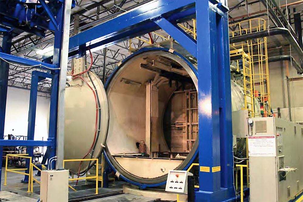
Heat Treatment for PM Gears: What HRC 58-62 Requires
Surface Hardness, Case Depth, and Core Strength: Separate Drawing Requirements
Achieving HRC 58–62 on powder metal gears requires more than one hardness value. Engineers must specify three separate properties: surface hardness to resist wear, case depth to support subsurface rolling-contact stresses, and core strength to handle bending loads at the tooth root. Wrought-steel drawings often combine these properties into simple callouts, but PM gears need clear targets for each zone. Surface-hardness measurements capture the wear layer, while case depth defines how far the hardened zone extends beneath the tooth flank. The core must retain enough ductility to absorb shock loads without brittle fracture.
These requirements work independently because porosity affects carbon and nitrogen penetration during heat treatment. A carburized PM gear can reach HRC 60 at the surface but still have inadequate case depth when the process time is reduced to control distortion. Surface-rolled gears need a densification depth that matches the subsurface stress profile, as with case depth in conventional carburizing. Research on surface-densified materials confirms that a minimum densification depth of about 0.5 mm helps prevent tooth-root bending failures. Specifications should define case depth at a stated hardness level rather than list only the surface value.
PM Density and Open Pores: Why Wrought-Steel Results May Not Transfer
Density determines whether a PM part behaves like wrought steel or needs modified heat-treatment protocols. Parts above 90 percent of theoretical density generally respond like wrought counterparts. Porosity reduces thermal diffusivity and hardenability at lower densities. The relationship follows a model in which thermal conductivity equals the matrix conductivity multiplied by one minus the fractional porosity. Reduced thermal diffusivity increases the time required to reach austenitizing temperature, which requires longer furnace cycles or higher setpoints.
Hardenability decreases because pores break up the continuous metal structure. Jominy tests on PM samples with densities between 76 and 91 percent showed lower hardness than wrought steel with the same chemistry. This reduction affects hardening depth and apparent surface hardness. Faster quenchants can offset the loss, but water-based media can cause internal corrosion when trapped in pores. Oil quenching remains standard, and fast oils around 9 GMQS can produce acceptable hardness gradients. Materials below 90 percent density also have open pore networks that let carburizing atmospheres penetrate deeper than in fully dense wrought steel. Internal diffusion can over-harden the core and reduce toughness.
Pressed-and-Sintered vs. MIM Gears: Differences That Affect Heat Treatment
Press-and-sinter gears compact metal powder in a die, eject the green part, and sinter it at about 75 percent of the melting temperature to bond the particles. Density usually ranges from 85 to 92 percent, depending on compaction pressure and powder characteristics. Lubricants mixed into the powder burn off during sintering and leave residual porosity. MIM gears use a different process. Metal powder is mixed with a binder that can account for 45 percent of the volume, injection molded into complex shapes, then debound and sintered. The high binder content supports intricate geometries but can cause shrinkage of up to 18 percent during densification.
Heat-treatment timing is different because MIM parts often reach higher final densities. Some approach full theoretical density after additional hot isostatic pressing. Press-and-sinter gears retain more open porosity, which increases carbon uptake but makes quench-media selection more difficult. MIM parts with interconnected porosity below 0.2 percent can receive standard plating and surface treatments without special preparation. Both processes allow carburization to increase surface hardness, but practitioners must confirm that part density, open-pore structure, and critical tolerances match the furnace atmosphere and quench method before releasing tooling.
Vacuum Carburizing vs. Carbonitriding: How Each Process Works
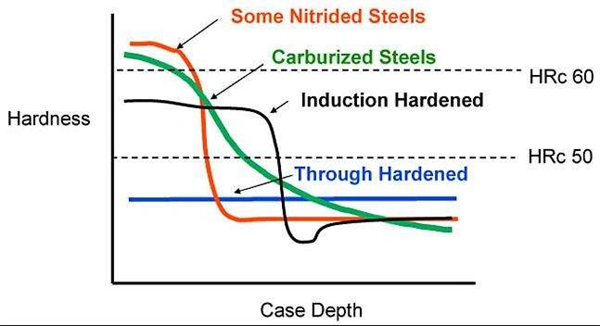
Carbon Diffusion Under Low Pressure vs. Carbon and Nitrogen Diffusion
Vacuum carburizing operates at pressures well below atmospheric pressure, typically 1–20 Torr. Hydrocarbon gasses break down without interference from equilibrium reactions under these conditions. Acetylene or propane enters the chamber, decomposes directly on the steel surface, and releases carbon atoms into the austenite matrix. The vacuum environment prevents oxidation and the water-gas reaction that limits atmosphere carburizing. Carbon transfer rates can therefore rise at equivalent temperatures. Intergranular oxidation does not occur because the low-pressure environment contains no oxygen or water vapor.
Carbonitriding changes the standard gas carburizing atmosphere by adding ammonia to the furnace. Ammonia dissociates at the work surface and releases nascent nitrogen, which diffuses into the steel with carbon. Both elements enter the austenite, but nitrogen lowers the critical cooling rate and raises case hardenability beyond carbon alone. The process uses lower temperatures than pure carburizing, typically 820–880°C, and produces shallower cases that are generally 0.075 to 0.75 mm deep. Nitrogen addition allows oil quenching for steels that would otherwise need water quenching after carburizing, which reduces distortion risk.
Vacuum Boost-and-Diffuse Cycles vs. Carbonitriding Atmosphere Control
Vacuum carburizing alternates between boost periods and diffusion periods. During boost periods, hydrocarbon gas flows into the chamber and carbon saturates the surface. During diffusion periods, the gas supply stops and carbon moves deeper into the part under vacuum. Each boost pulse lasts about 90 seconds at the target carburizing pressure before evacuation. The cycle repeats until the required case depth forms. This pulsed method prevents soot formation and controls the carbon concentration gradient through changes to boost duration and diffusion intervals.
Carbonitriding maintains a continuous atmosphere of carrier and enriching gasses plus ammonia throughout the cycle. The ammonia fraction dilutes the atmosphere and affects carbon potential measurements. Operators monitor oxygen potential or dew point to maintain the correct carbon activity, and ammonia flow controls nitrogen pickup. Nitrogen absorption depends on the furnace atmosphere’s free ammonia content rather than the ammonia percentage in the inlet gas. Carbonitriding becomes less effective as process temperature rises because ammonia decomposes spontaneously at higher temperatures.
Process Temperature and Time: Effects on Grain Growth and Carbon Uptake
Carbonitriding temperatures range from 820 to 880°C, which is well below the 900–950°C range used for gas carburizing. Lower processing temperatures limit austenite grain growth and produce finer grain structures after quenching. Carburizing at 930°C and then carbonitriding at 850°C can optimize microstructure and wear resistance in alloy steels. Raising the carbonitriding temperature to 880°C promotes grain coarsening, reduces carbide fraction, and increases retained austenite content.
Vacuum carburizing typically operates between 920 and 1080°C. Higher temperatures accelerate carbon diffusion and reduce total cycle time to one-half or one-third of conventional carburizing time. This higher temperature range is practical because the vacuum environment prevents oxidation that would damage surfaces in atmosphere furnaces.
Oil vs. Gas Quenching: Options Depend on Alloy, Density, and Section Size
Oil quenching remains standard for carbonitrided parts because nitrogen-boosted hardenability provides adequate hardness at oil’s slower cooling rates. Fast oils are used for PM gears to offset the lower hardenability caused by porosity. Vacuum carburizing systems can use oil quenching or high-pressure gas quenching at 6–20 bar with nitrogen, helium, or argon. Gas quenching removes the vapor blanket stage that causes uneven cooling in oil and produces more consistent case depth across gear tooth flanks and roots. Section thickness and alloy hardenability determine whether gas quenching can cool the material fast enough to form martensite throughout the case.
Case Depth and Gear Fatigue: Comparing Load Support
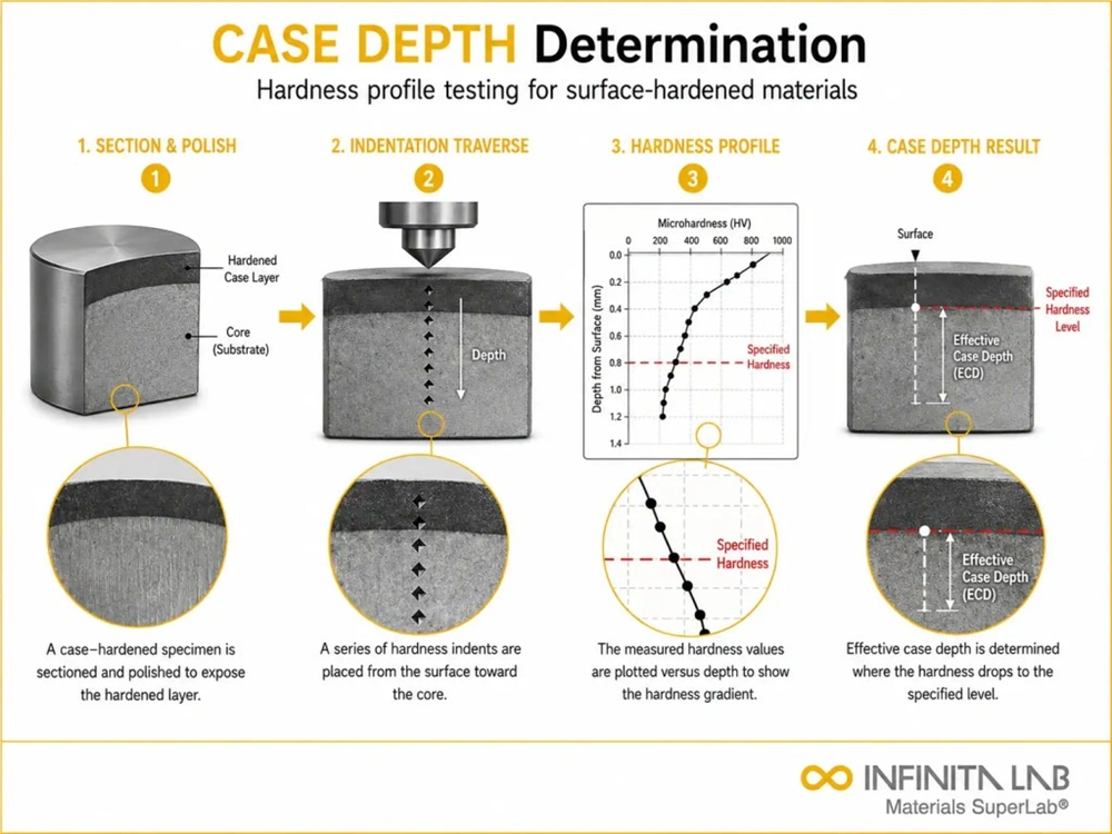
Deeper Carburized Cases vs. Typically Shallower Carbonitrided Cases
Vacuum carburized cases often range from 0.76 to 1.32 mm deep, providing strong sub-surface load support for high-contact-stress applications where subsurface load support dictates service life. Carbonitrided cases remain shallower, typically 0.075 to 0.75 mm, because lower processing temperatures and added nitrogen limit inward carbon diffusion. This difference determines how each treatment supports cyclic contact loads and fits applications where surface wear determines replacement intervals.
Tooth Flank Pitting vs. Root Bending: Matching the Case to the Stress
Gears face different failure modes at the flank and root. The flank experiences high Hertzian contact stresses that cause micropitting and sub-surface shear. Deeper carburized cases support these flank loads without yielding. The tooth root experiences high tensile bending stresses during power transmission. A case that is too deep can consume too much ductile core, leaving the tooth vulnerable to brittle root-bending fatigue. Matching case depth to the stress gradient prevents both flank pitting and root fracture.
Internal Hardening Through Open Pores: Risks to Core Toughness
PM parts with interconnected open porosity allow carbon and nitrogen to penetrate deep into the interior during carburizing or carbonitriding. This internal diffusion hardens the core unintentionally, reducing impact toughness and increasing fracture risk. Engineers must seal pores via resin impregnation or surface densification, or adjust boost-diffusion cycles to limit deep penetration in lower-density components.
Distortion and Surface Quality After Each Treatment
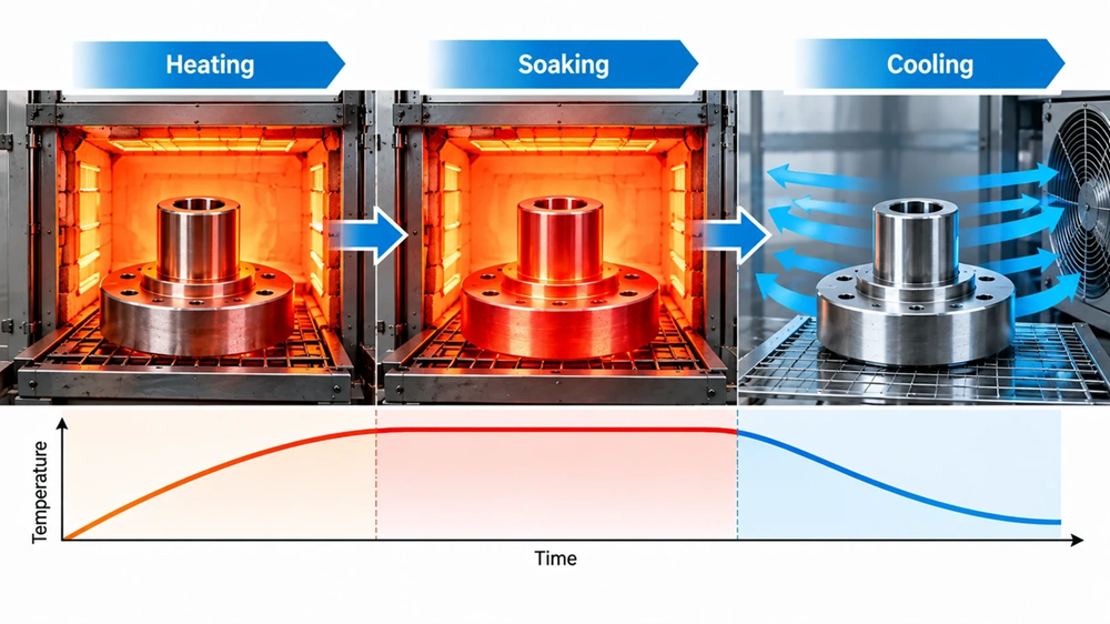
Case Uniformity, Fixturing, and Quench Flow: Drivers of Size Change
Distortion during heat treatment depends on part geometry, heating uniformity, case uniformity, fixturing, and quench flow dynamics. Symmetrical gears distort predictably when supported in dedicated fixtures. High-pressure gas quenching in vacuum furnaces allows directional cooling control, reducing distortion compared to traditional oil baths where thermal gradients fluctuate across complex tooth geometries.
Vacuum Processing and Intergranular Oxidation: Differences from Gas Carbonitriding
Vacuum processing eliminates intergranular oxidation (IGO) because the chamber contains no oxygen or water vapor. IGO weakens the fatigue strength of gas-carburized wrought and PM gears unless manufacturers grind away the affected surface layer. Carbonitriding introduces reactive gasses and can form minor oxidation layers, requiring careful atmosphere monitoring.
Grinding Allowance: Preserving the Hardened Case on Finished Teeth
Heat treatment alters dimensions, so manufacturers leave a grinding allowance on critical tooth flanks. If the allowance is too small, grinding removes the hardened case, exposing softer core material. If too large, grinding costs rise and cycle times increase. Vacuum carburizing provides uniform case depth, preserving the hardened case on finished teeth and allowing predictable grinding allowances.
Need Expert Heat-Treatment & Gear DFM Guidance?
Achieving HRC 58-62 on PM and MIM gears requires precise control over density, case depth, and distortion. Let JHMIM optimize your gear manufacturing and heat-treatment specifications.
Contact JHMIM’s Engineering Team Today for a Free DFM Review & Quote →
Verifying HRC 58-62 on Carburized Powder Metal Gears
Apparent Rockwell Hardness vs. Matrix Microhardness in Porous Steel
Testing hardness on porous PM steel requires specialized methods. Standard Rockwell indentation (HRC) flattens local pores, giving artificially low readings known as apparent hardness. True material strength is measured using Vickers or Knoop microhardness on individual sintered particles (matrix microhardness), ensuring the steel microstructure actually meets the HRC 58–62 target.
Microhardness Traverses: Checking Case Depth at the Flank and Root
Quality control requires microhardness traverses from the surface inward to the core. Technicians measure Vickers indentations at fixed intervals across both the tooth flank and the root fillet to map case depth profile and verify that surface hardening meets engineering drawings.
Metallography: Checking Pores, Carbides, Retained Austenite, and Core Structure
Metallographic examination inspects polished cross-sections for pore morphology, carbide precipitation, retained austenite levels, and grain boundary condition. Excessive retained austenite softens the case, while grain boundary carbides can cause brittleness.
Gear Metrology and Load Tests: Confirming Accuracy and Fatigue Performance
Final validation uses gear rolling testers and coordinate measuring machines (CMM) to check lead, profile, and runout errors. Dynamic dynamometer testing confirms that treated gears survive high-torque fatigue cycles under operating loads.
Cost and Selection: When Each Process Fits PM Gears
Vacuum Equipment Cost vs. Carbonitriding Batch Cost: What Supplier Quotes Must Include
Vacuum furnaces require high capital investment, resulting in higher equipment amortization costs per batch. Carbonitriding batch furnaces have lower equipment costs but incur ongoing expenses for atmosphere gasses, endogenerators, and maintenance. Supplier quotes must itemize furnace time, gas consumption, and secondary machining or grinding.
Total Finished-Part Cost: Cycle Time, Grinding, Inspection, and Scrap
Evaluating heat treatment costs requires looking at the total finished-part budget. Although vacuum carburizing has higher upfront processing costs, its superior distortion control and clean surfaces reduce post-heat-treat grinding and scrap rates. Carbonitriding offers lower initial processing costs but may increase finishing expenses if distortion requires extensive correction.
Selection Checklist: Deep-Case Loads vs. Shallow-Case Needs and Available Capacity
The decision depends on load requirements and budget. Applications that just need deep cases can justify investment in vacuum equipment. Shallow-case requirements favor carbonitriding’s throughput and lower capital costs. Part density and section thickness, along with available heat-treat capacity, complete the selection matrix. Match the process to the stress field, not the other way around.
- Deep-Case & High Load: Select vacuum carburizing when case depth must exceed 0.75 mm and applications demand maximum subsurface fatigue resistance.
- Shallow-Case & Cost Efficiency: Select carbonitriding for shallow wear layers (0.075–0.75 mm) where high-volume throughput and lower capital costs dictate production.
- Density & Porosity Check: Confirm part density, open pore connectivity, and section size before locking in the heat-treatment route.
Conclusion: Partner with JHMIM for Precision Heat-Treated Gear Manufacturing
Both vacuum carburizing and carbonitriding can push PM and MIM gears into the HRC 58–62 range, but they follow different paths. Vacuum carburizing delivers deeper cases between 0.76 and 1.32 mm for high-contact-stress applications where subsurface load support determines service life. Carbonitriding finishes faster and produces cases from 0.075 to 0.75 mm, fitting production environments where surface wear determines replacement intervals.
Selecting the optimal heat-treatment route requires balancing density, tooth geometry, mechanical stress fields, and total component budget. At JHMIM, we combine advanced powder metallurgy and metal injection molding with tight-tolerance heat treatment controls—ensuring peak surface hardness without compromising core toughness or dimensional accuracy.
Ready to optimize your custom gear manufacturing? Contact JHMIM’s engineering team today or upload your 3D CAD drawings for a comprehensive DFM and heat-treatment evaluation within 24 hours.
FAQs
Q1. Can both vacuum carburizing and carbonitriding achieve HRC 58–62 on powder metal gears?
Yes. Both can reach this surface hardness range, but success depends on the alloy, part density, treatment cycle, and quenching method. Case depth and core strength must also meet separate requirements.
Q2. When should you choose vacuum carburizing over carbonitriding?
Choose vacuum carburizing when gears need a deeper hardened layer to support high contact loads. Carbonitriding suits shallower wear-resistant layers, typically 0.075–0.75 mm, and faster production cycles.
Q3. How does porosity affect heat treatment of powder metal gears?
Open pores let carbon and nitrogen penetrate beyond the intended surface layer, potentially hardening the core and reducing toughness. Porosity also affects cooling and hardness readings, so treatment must match the gear’s density.
Q4. Which process produces less distortion and a cleaner surface?
Vacuum carburizing avoids intergranular oxidation and can use gas quenching for more uniform cooling. However, distortion with either process depends on gear shape, fixturing, alloy, and quench conditions.
Q5. How should hardness and case depth be checked on PM gears?
Use surface hardness testing alongside microhardness measurements from the surface toward the core at the tooth flank and root. Rockwell readings alone can be misleading because pores affect the result.