
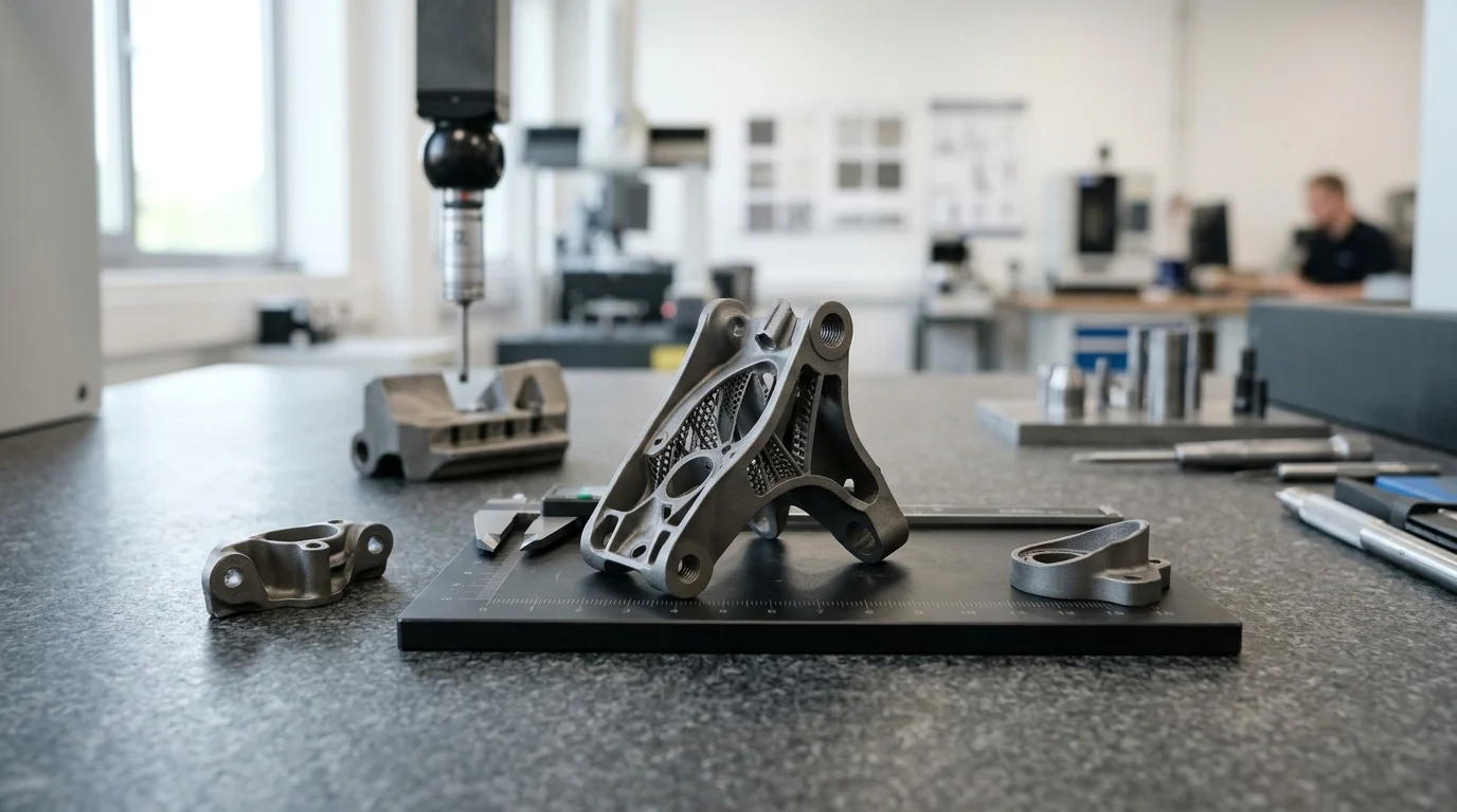
Dimensional accuracy and shape retention represent the most demanding engineering challenges in manufacturing advanced titanium components via Metal Injection Molding (MIM). This is particularly true when parts combine ultra-thin walls, long unsupported spans, asymmetric structural features, and strict geometric dimensioning and tolerancing (GD&T) requirements. During high-temperature thermal consolidation, titanium MIM parts undergo 12% to 18% volumetric shrinkage. Minor variations in binder distribution, wall thickness ratios, setter friction, or thermal gradients can easily turn this shrinkage into unacceptable warping, sag, or geometric distortion. For aerospace, medical implant, and high-performance industrial applications, preventing distortion directly impacts yield, piece-part cost, and the necessity for secondary machining. This guide details the root mechanisms of titanium MIM distortion and provides practical Design for Manufacturability (DFM) rules and process controls to guarantee dimensional stability.
Why Distortion and Warping Occur in Titanium MIM
Metal Injection Molding (MIM) enables the mass production of complex, high-performance titanium alloy components. However, achieving strict dimensional fidelity remains a formidable metallurgical challenge. The primary hurdle is managing the massive, isotropic volumetric shrinkage during thermal sintering (typically 12% to 18% linear contraction). When densification occurs non-uniformly across a component, it manifests as warping, twisting, or dimensional out-of-spec conditions.
Popular titanium alloys—such as Ti-6Al-4V (Grade 5) and Ti-6Al-4V ELI (Grade 23)—exhibit extreme chemical reactivity at elevated temperatures, requiring high-vacuum thermal sintering (frequently below 10-4 mbar) or ultra-pure argon gas protection. At peak sintering temperatures (1,250°C to 1,400°C), titanium transitions into its high-temperature beta phase, leaving the material exceptionally plastic and susceptible to gravity-induced creep and mechanical drag.
Key Causes of Distortion, Warping, and Shrinkage Variation
Distortion in titanium MIM components originates from two primary stages: green-body density gradients created during injection molding and thermal-mechanical forces during debinding and sintering.
During the molding phase, high shear forces can induce binder migration, creating localized variations in the powder-to-binder loading ratio. Regions with higher polymer content possess lower green powder density and experience greater volumetric shrinkage during sintering.
During sintering, as the part consolidates from a porous “brown body” (~60% solid density) to a dense metal structure (>96% theoretical density), physical friction between the shrinking component and the ceramic furnace setter plate restricts bottom-face movement. Because the upper section contracts freely while the bottom interface is constrained by frictional drag, shear stresses warp the component’s edges upward. Furthermore, the low yield strength of titanium at peak sintering temperatures makes thin, unsupported features vulnerable to gravitational sag.
High-Risk Geometry Features in Complex Titanium MIM Parts
Specific design features significantly increase warping risks during thermal processing:
- Abrupt Wall Thickness Variations: Thickness transitions exceeding a 3:1 ratio cause thin sections to heat and densify faster than thick bosses, creating internal thermal stresses that warp the geometry.
- Unsupported Cantilevers & Spans: Overhanging features or unsupported spans exceeding 15 mm exhibit severe gravitational sag at peak temperatures.
- Ultra-Thin Sections: Walls thinner than 0.5 mm lack structural stiffness during binder burnout, making them prone to buckling.
- Asymmetric Geometries: Asymmetrical mass distributions cause uneven thermal absorption and non-uniform shrinkage vectors.
Process Controls That Reduce Distortion

Mitigating distortion requires systematic control throughout the entire MIM manufacturing value chain—from feedstock formulation and cavity filling to thermal profiling and specialized ceramic fixturing.
Feedstock Quality, Mold Filling Balance, and Binder Removal
Stabilizing dimensions starts with feedstock homogeneity. Titanium MIM feedstocks typically maintain a powder loading of 62% to 65% by volume using spherical gas-atomized titanium powder. Inadequate mixing creates micro-density gradients that manifest as warpage after sintering. During molding, gate location and runner geometry must ensure balanced flow fronts, minimizing weld lines and localized shear stress.
Multi-stage debinding (combining solvent extraction with thermal debinding) must be tightly controlled. Outgassing of polymer binders must occur at a rate that prevents internal pressure buildup. Rapid heating during debinding can cause micro-cracking, swelling, or distortion in the fragile brown part prior to thermal necking.
Sintering Profile, Furnace Atmosphere, and Part Support
Titanium MIM sintering demands precise thermal uniformity across the hot zone (ideally within ±5°C). Temperature gradients induce differential densification rates across the part, triggering warping.
To counteract frictional drag and gravity sag, specialized setter fixtures are essential:
- Yttria/Zirconia Setters: Machined ceramic setters coated with yttria prevent chemical reaction (alpha-case formation) between the reactive titanium and the substrate.
- Live Setters (Sacrificial Supports): Molded from the identical titanium feedstock formulation, live setters shrink dynamically at the exact same rate as the target component, neutralizing friction-induced drag stresses at interface surfaces.
How to Choose the Best Prevention Strategy
Selecting the optimal distortion prevention strategy requires balancing tolerance requirements, production volumes, and tooling budgets. Minor warpage can often be resolved through DFM adjustments, whereas complex geometries demand custom setters, mold windage compensation, or secondary post-processing.
Comparison Points for Evaluating Distortion Risks
Standard as-sintered titanium MIM holds linear tolerances of ±0.3% to ±0.5%. When tight geometric tolerances are specified, engineers should evaluate the relative setup cost and lead time of various mitigation strategies:
| Mitigation Strategy | Typical Tolerance Capability | Relative Setup Cost | Implementation Lead Time |
|---|---|---|---|
| Standard Flat Setters | ±0.5% | Low | None |
| Tooling Windage Compensation | ±0.3% | High | 3 to 6 weeks |
| Custom Ceramic / Live Setters | ±0.2% | Medium | 2 to 4 weeks |
| HIP + Secondary Coining / Machining | ±0.1% or tighter | Very High | 1 to 2 weeks (recurring) |
*Note: Tolerances of ±0.1% require secondary sizing, coining, or precision CNC machining operations following Hot Isostatic Pressing (HIP) to guarantee critical dimensional features.
Key Takeaways
- Design titanium MIM components with gradual wall-thickness transitions, avoiding ratios greater than 3:1 to eliminate differential thermal contraction.
- Identify unsupported overhanging spans greater than 15 mm and walls under 0.5 mm as high-risk features requiring custom ceramic setter support.
- Maintain feedstock powder loading (62%–65% by volume) and balanced gate placement to eliminate green-density gradients before thermal processing.
- Account for 12% to 18% volumetric shrinkage during high-vacuum sintering when defining mold cavity scaling factors and inspection datums.
- Utilize dynamic “live setters” or yttria-coated ceramic plates to counteract high-temperature friction drag and gravitational creep.
Frequently Asked Questions
Why do titanium MIM parts warp during high-temperature sintering?
Titanium MIM parts undergo 12% to 18% volumetric shrinkage during sintering. Friction against ceramic setter plates, gravity-induced creep, green-density variations, and titanium’s high plastic deformation in the beta-phase regime at peak temperatures (1,250°C–1,400°C) cause non-uniform contraction, manifesting as warping.
Which titanium MIM geometries are most vulnerable to distortion?
High-risk geometries include long unsupported spans (>15 mm), thin walls (<0.5 mm), large flat plates lacking stiffening ribs, and components with wall-thickness ratio changes exceeding 3:1.
How does wall thickness variation impact titanium MIM shrinkage?
Thin wall sections heat up and densify faster than heavy structural bosses. When wall transitions are abrupt, this densification rate mismatch generates internal shear stresses that pull the part out of alignment.
Can mold tooling compensation prevent warping in titanium MIM components?
Mold compensation (adding “windage” to mold cavities) effectively counteracts predictable, repeatable warping vectors. However, it must be paired with homogeneous feedstock, balanced injection gating, and stable furnace setters to achieve tight dimensional control.
Why is titanium more challenging to sinter accurately than stainless steel MIM?
Titanium alloys (such as Ti-6Al-4V) are highly reactive and require ultra-high-vacuum sintering environments. At peak temperatures, titanium exhibits lower yield strength and higher plastic creep than stainless steels, making parts significantly more susceptible to gravity sag and setter drag.