
Custom Oil-Impregnated Bronze Bushings: Manufacturing, Material Grades & Design Guide
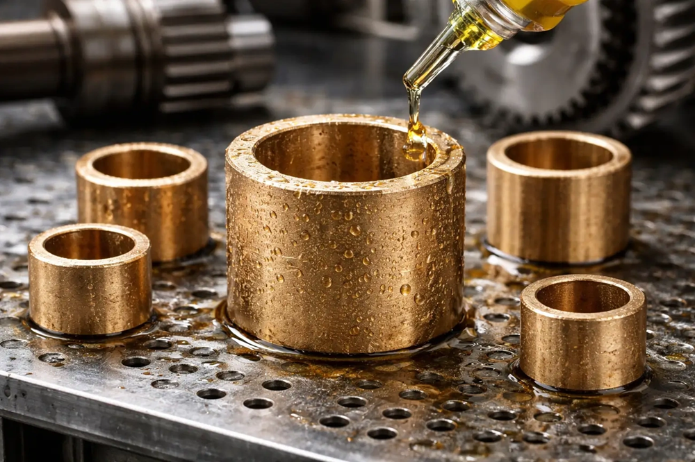
Oil impregnated bronze bushings deliver exceptional performance through controlled porosity, typically 15-30% by volume, which stores lubricant for continuous self-lubrication. These self-lubricating bronze bushings can achieve service lives up to 50,000 hours with oil content ranging from 9% to 27%. Understanding what sintered bronze is, how oil impregnated bronze is made, and the manufacturing process matters for optimal component selection. We get into sintered bronze SAE 841 standards, material composition and sintered bronze bushing tolerances here, along with custom design parameters. Engineers will find specifications for porosity control, PV limits and application-specific configurations.
What is Sintered Metal and How Oil-Impregnated Bushings Work
Sintered bronze emerges from a controlled powder metallurgy process where metal particles bond without fully melting. This manufacturing route creates the interconnected pore network that distinguishes oil-impregnated bronze from cast or machined alternatives.
Powder Metallurgy Manufacturing Process
The transformation begins with powder blending. Copper and tin powders combine to precise bronze compositions of 90% Cu and 10% Sn, with 0.3-2 wt% zinc stearate lubricant added. The homogeneous mixture feeds into precision steel dies to compact.
Compaction subjects the powder to pressures between 200-600 MPa and forms a “green compact” with controlled density between 6.5-7.2 g/cm³. The part holds its shape but lacks mechanical strength at this stage. The powder particles remain bonded loosely and require further processing to achieve structural integrity.
Sintering follows at temperatures ranging from 750-900°C in a protective atmosphere furnace. The temperature remains below bronze’s melting point and allows particles to bond through diffusion and recrystallization without changing the component’s shape. This critical step creates permanent inter-particle bonds while preserving the interconnected capillary network throughout the structure. Heating rates during dewaxing exceed 50°C/min to prevent binder accumulation that causes surface defects.
Sizing represents an optional refinement step. The sintered part receives additional pressing at room temperature to correct dimensional shrinkage and achieve final tolerances while maintaining internal porosity. This controlled deformation improves surface finish and dimensional accuracy.
Vacuum oil impregnation completes the process. The chamber evacuates to about 50 mbar and removes air from the pore structure. Heated lubricating oil then floods the chamber, and capillary action draws fluid through the porous matrix. The result is a self-contained lubricant reservoir within the bronze structure.
Self-Lubricating Mechanism: Thermal Expansion and Capillary Action
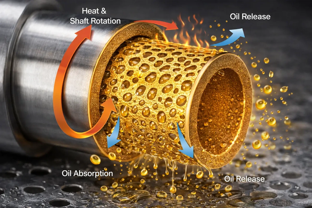
The operational principle relies on thermal dynamics and fluid physics working together. Shaft rotation generates frictional heat at the bearing surface. This localized temperature rise causes the impregnated oil to expand at a higher thermal rate than the surrounding bronze structure.
Thermal expansion forces oil from the capillary pores onto the bearing surface and creates a lubricating film between the shaft and bushing. This released oil forms a hydrodynamic wedge at higher speeds that separates metal surfaces and minimizes direct contact. The process operates during machinery operation, with heat and capillary forces drawing oil to the friction interface.
Capillary pressure reverses the flow whenever the shaft stops and temperature drops. The oil migrates back into the pore network and is stored there until the next operational cycle. This self-regulating mechanism eliminates external lubrication requirements throughout the bearing’s service life.
Porosity Structure: 15-30% Oil Reservoir Capacity
The interconnected pore structure represents 15-30% of total component volume, with some applications extending to 40%. These microscopic channels serve dual functions: oil storage and lubricant transport pathways. Pore size distribution between 5-50 μm with greater than 90% surface connectivity determines oil retention capacity.
Oil content ranges from 15-30 vol%, though standard applications achieve 18-25%. The porosity-strength relationship creates design constraints. Insufficient porosity limits oil storage and accelerates bearing failure through lubricant depletion. Excessive porosity compromises load-bearing capacity and crush strength. The controlled 20-30% range balances mechanical properties with lubrication performance.
Thermal cycling between -40°C and 150°C drives the oil pumping action. Expansion and contraction flush wear debris into the pore network while delivering fresh lubricant to sliding surfaces. This exchange maintains film integrity across varying operating conditions.
Material Grades and Composition Specifications
Material selection determines bearing performance in load, speed and environmental conditions. Sintered bronze SAE 841 serves as the industry reference standard, with additional MPIF grades addressing specialized requirements.
Sintered Bronze SAE 841 Standard Properties
SAE 841 specifies a controlled composition range: 87.5-90.5% copper, 9.5-10.5% tin, with carbon limited to 1.75% maximum and iron to 1% maximum. The standard mandates density between 6.4-6.8 g/cm³ to oil-impregnated parts, with minimum porosity of 19% by volume. This porosity target balances mechanical strength against oil storage capacity.
Mechanical properties have a K-strength constant of 26,500 psi, yield strength in compression of 11,000 psi and tensile strength reaching 14,000 psi. The material exhibits minimal elongation of 1% in one inch. This reflects its brittle nature compared to wrought bronzes. Rockwell hardness measures H-45 in the as-sintered condition.
ASTM B-438-05 Grade 1 Type II, Military specification MIL-B-5687D and MPIF designation CT-1000-K26 are equivalent to the standard. These equivalent specifications ensure cross-industry compatibility to bearing applications.
CuSn10 Alloy Composition: 87-90% Cu, 9.5-10.5% Sn
CuSn10 represents the foundational alloy system to oil-impregnated bronze bushings. The copper content ranges from 87-90% with tin controlled between 9.5-10.5%. Several MPIF variants exist within this composition framework. Grade CT-1000-K19 contains 87.2-90.5% copper and achieves minimum crushing strength of 130 MPa with 24% minimum oil content. The higher-density CT-1000-K40 maintains identical copper and tin ranges but reaches 280 MPa crushing strength while accommodating only 9% minimum oil.
Graphite additions create specialized grades. CTG-1001-K17 incorporates 0.5-1.8% graphite alongside 85.7-90.0% copper and delivers 120 MPa strength with 22% oil content. The high-graphite CT-1004-K10 formula has 2.5-5.0% graphite with 82.8-88.3% copper. This produces lower 70 MPa strength but maintains 11% oil capacity.
Density Ranges: 5.4-6.4 g/cm³ Trade-offs
Density influences the oil-to-strength relationship. Lower-density materials between 5.4-5.8 g/cm³ retain 20-25% oil by volume and create substantial lubricant reservoirs. This configuration suits low-speed applications where extended oil supply outweighs load requirements. The reduced compaction produces more interconnected porosity but limits load capacity.
Higher densities from 6.0-6.4 g/cm³ store only 12-18% oil yet withstand pressures reaching 10-14 MPa. The tighter particle packing increases mechanical strength while restricting pore volume. Engineers balance this trade-off based on application demands.
Oil Content by Application: 12-25% Volume Selection
Application conditions dictate optimal oil content. High-speed operations above 500 RPM just need 12-15% oil in 6.2-6.4 g/cm³ material. The reduced oil volume prevents seepage under centrifugal forces while maintaining dimensional stability. Heavy-load scenarios at 10-14 MPa demand 20-25% oil in lower 5.4-5.8 g/cm³ density structures. The expanded reservoir compensates for accelerated consumption under contact pressure.
Oscillating motion applications specify 18-22% oil with 5.8-6.2 g/cm³ density. Reciprocating action disrupts complete film formation, and elevated reserves sustain boundary lubrication. Temperature-cycling environments benefit from 18-22% content, as thermal expansion-contraction cycles just need sufficient reserves to maintain surface coverage.
Manufacturing Process: From Powder to Oil Impregnat
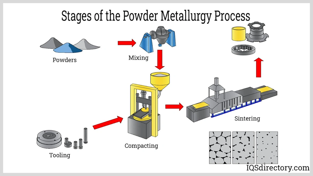
Transforming bronze powder into functional self-lubricating bushings requires four distinct manufacturing stages. Each stage controls specific properties that determine final bearing performance.
Compaction: 200-600 MPa Pressure in Steel Dies
Blended bronze powder feeds into precision-machined steel dies. Hydraulic presses apply 200-600 MPa there. This pressure range compacts particles into green bushings with simple shape retention but limited mechanical strength. Compaction pressure directly influences green density, which affects sintered density and final mechanical properties. Higher pressures create greater contact points among powder particles and lead to plastic deformation. This forms original bonds and reduces porosity.
Studies demonstrate that increasing compaction pressure from 550 to 750 MPa lifts sample density from 7.04 to 7.24 g/cm³. Hardness rises from 83 to 119 HV 0.5 at the same time. The green compact maintains around 65-70% of theoretical density at this stage. This provides sufficient handling strength to transfer to sintering furnaces without structural failure.
Sintering Cycle: 750-900°C in Protective Atmosphere
Sintered bushings undergo heating at 750-900°C in continuous furnaces with protective atmosphere control. Bronze particles bond through solid-state diffusion and maintain an interconnected pore structure of 9-27%. The temperature remains below bronze’s melting point. This allows particle fusion at contact points without collapsing the component geometry.
Protective atmosphere composition substantially affects physical and mechanical properties of sintered bronze components. Furnace atmosphere flow rate influences dimensional stability and microstructural characteristics, among particle size distribution and sintering duration. The sintering cycle preserves the capillary network needed for oil storage and transport.
Sizing for IT5-IT7 Dimensional Accuracy
Post-sintering sizing operations improve dimensional precision to IT5-IT7 tolerance grades. Radial dimensional accuracy after original sintering ranges from IT8 to IT9. Parts expand 1-3% during the heating cycle. Sizing involves repressing sintered bushings to correct dimensions and achieves tolerances as tight as ±5 μm for small components. Diameter accuracy improves to IT5-IT7 for self-lubricating bushings. Length tolerances remain broader at IT12.
Vacuum Oil Impregnation: Filling 9-27% Pore Volume
Vacuum impregnation saturates the porous structure with lubricating oil. Bushings enter sealed chambers where vacuum pumps evacuate air from interconnected pores. Pre-heated oil floods the chamber once stable vacuum conditions exist. Atmospheric pressure returning forces oil deep into the evacuated pore network and fills around 9-27% of total component volume. This saturation transforms the porous bronze shell into a self-lubricating bearing. The bearing now has integral oil reserves distributed throughout the metallic matrix.
Custom Design Parameters: Tolerances, Clearances & PV Limits
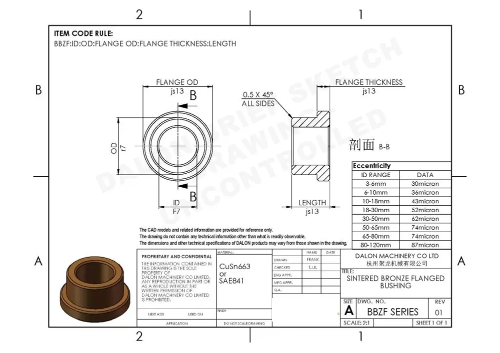
Precision engineering requirements define the performance boundaries of self-lubricating bronze bushings in mechanical systems of all types. Dimensional accuracy, clearance calculations and load-speed parameters establish reliable operation within specified service conditions.
Sintered Bronze Bushing Tolerances: ±0.01mm After Sizing
Oil impregnated bronze bushings achieve radial tolerance within ±0.01mm after the sizing operation. This precision controls both inner diameter clearance with the shaft and outer diameter interference with the housing bore. The sizing process delivers an additional benefit: surface sealing of the porous structure. This prevents oil migration through the outer diameter during press-fit installation.
Running Clearance: 0.001-0.002mm per mm Shaft Diameter
Diametral clearance between the bushing bore and shaft requires 0.001-0.002mm per mm of shaft diameter. To name just one example, a 25mm shaft needs 0.025-0.050mm total diametral clearance. Insufficient clearance squeezes out the oil film and triggers metal-to-metal contact. Excessive clearance reduces load capacity and introduces vibration. Applications experiencing 80-100°C temperature excursions just need additional clearance to prevent seizure from differential thermal expansion between shaft and housing materials.
PV Limit Calculations: 1.75 N/mm²·m/s Standard Grade
Standard grade oil impregnated bushings operate at PV limits of 1.75 N/mm²·m/s during continuous service. Pressure (P) calculates as bearing load divided by projected area (length × diameter). Velocity (V) represents shaft surface speed in meters per second. Exceeding this threshold generates frictional heat faster than the bearing dissipates it. This causes oil degradation and wear at an accelerated rate.
Shaft Hardness Requirements: 35-55 HRC
Hardened shafts rated 35-55 HRC provide optimal wear resistance for sintered bronze bushings. The minimum hardness of 35 HRC (327 HV) prevents the softer bronze from embedding into the shaft surface, which creates clearance loss and vibration. Optimal performance occurs between 45-55 HRC (450-590 HV). Surface roughness between 0.2-0.8 μm Ra complements proper hardness.
Press-Fit Effects: Bore Close-In and Post-Installation Machining
Press-fitting compresses the bushing structure and transfers 60-80% of housing interference to the bore diameter. Standard press-fit interference ranges from 0.025-0.075mm depending on wall thickness. This radial compression reduces the internal diameter after installation compared to free-state dimensions. Sizing or reaming after press-fit installation restores precise bore dimensions and consistent porosity distribution throughout the bearing surface.
Application Selection and Custom Configuration Options
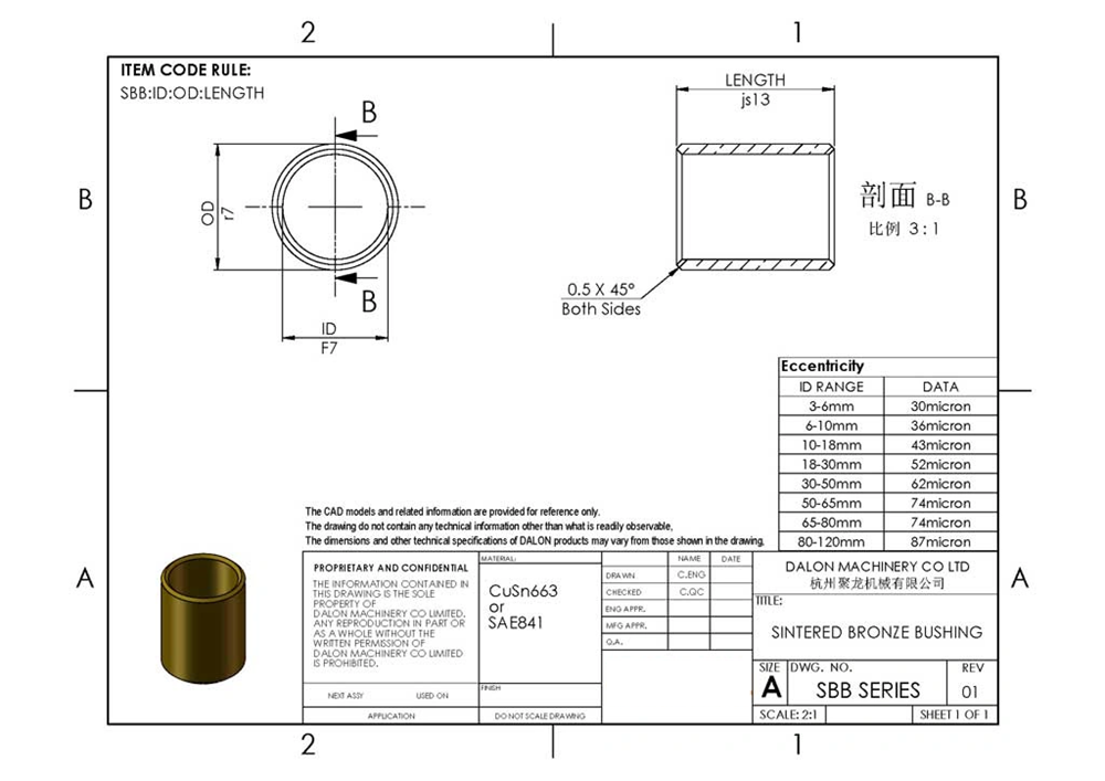
Successful bearing implementation calls for matching component specifications to actual operating conditions rather than relying on generic self-lubricating claims.
Load, Speed, and Duty Cycle Evaluation
Load patterns just need realistic assessment beyond nominal ratings. Radial loads, axial influences and dynamic variations affect performance. Shock loading and misalignment-related stresses also play a role. Sintered bronze bushings suit light to moderate-duty applications. Heavier or erratic loads call for closer review. Speed alone misleads without thinking over load, duty cycle and temperature together. Continuous versus intermittent operation changes bearing demands by a lot. Start-stop patterns create different requirements than smooth continuous running.
Custom Geometries: Sleeve, Flanged, Spherical Shapes
Cylindrical sleeve bearings reduce friction under heavy loads and high temperatures. Flanged configurations provide axial location and simplified installation. Single flanges handle unidirectional thrust while double flanges manage bidirectional forces. Spherical designs accommodate misalignment through concave inner surfaces and distribute loads evenly.
Oil Groove Patterns for Faster Break-In
Groove patterns accelerate break-in from 24 hours to 4-8 hours by distributing oil faster across the bearing’s surfaces. Figure-eight patterns suit rotating shafts with periodic greasing. Straight axial grooves serve reciprocating motion. Spiral configurations move lubricant along bearing length during continuous rotation.
Material Selection for Temperature and Environment
Operating temperatures above 300°F call for graphite plugging as oils and greases degrade. Aluminum bronze handles marine environments and corrosive conditions well. Contaminated environments benefit from 20-25% oil content with loose clearances.
Conclusion & Custom DFM Evaluation
Oil-impregnated bronze bushings represent a precise balance between controlled porosity and mechanical strength. The interconnected pore structure ranges from 15-30% by volume and enables self-lubrication through thermal expansion and capillary action. Engineers now possess detailed specifications for material selection, from SAE 841 standards to density-dependent oil content ratios. The manufacturing sequence transforms bronze powder into precision components that achieve IT5-IT7 tolerances after sizing operations. Successful implementation depends on matching PV limits and running clearances to actual operating conditions rather than nominal ratings. Custom geometries and oil groove patterns optimize performance further in a variety of applications. Proper specification yields service lives approaching 50,000 hours without external lubrication requirements.
Need Custom Sintered Bronze Bushings for Your Project? Send your 3D CAD models (.STEP / .DWG) to JHMIM. Our powder metallurgy engineers will review your tolerances and provide a free DFM feasibility evaluation and competitive quote within 24 hours.
Phosphor bronze and bearing bronze are recognized for their superior wear resistance, making them excellent choices for bushing applications where durability and longevity are critical requirements.
Oil-impregnated bronze bushings typically exhibit a hardness range of 45-65 HB (Brinell hardness). This softer hardness compared to the mating shaft allows the bushing to embed debris particles without damaging the shaft surface.
Bronze bushings typically achieve inner diameter (ID) tolerances of approximately 0.065 mm and outer diameter (OD) tolerances around 0.030 mm. After sizing operations, sintered bronze bushings can reach even tighter tolerances of ±0.01 mm for precision applications.
The recommended diametral clearance is 0.001-0.002 mm per millimeter of shaft diameter. For example, a 25 mm shaft would require a total diametral clearance of 0.025-0.050 mm to ensure proper oil film formation and prevent metal-to-metal contact.
Shafts should be hardened to 35-55 HRC (Rockwell hardness) for optimal performance. The minimum hardness of 35 HRC prevents the bronze from embedding into the shaft surface, while the range of 45-55 HRC provides the best wear resistance and longevity.