
The Engineering Guide to Rockwell Hardness Test: Methods, Standards, and Applications

The Rockwell hardness test stands as one of the most prominent methods to measure material hardness in modern industry. This testing method delivers immediate results by measuring indentation depth rather than width. Speed, repeatability, and direct reading capabilities make it valuable. Engineers rely on the Rockwell hardness tester for production control, incoming inspection, and heat treatment verification applications. You need to understand Rockwell scales, interpret the Rockwell hardness chart, and know what Rockwell hardness means to characterize materials with precision. This applies whether you evaluate heat-treated steel or softer alloys. This piece explores core testing principles and compliance with ASTM E18 and ISO 6508 standards. It covers practical applications and comparisons including Brinell vs Rockwell hardness test methods.
Core Principles and Mechanics of the Rockwell Hardness Test
The Indentation Depth Metric: How Rockwell Differs from Brinell and Vickers
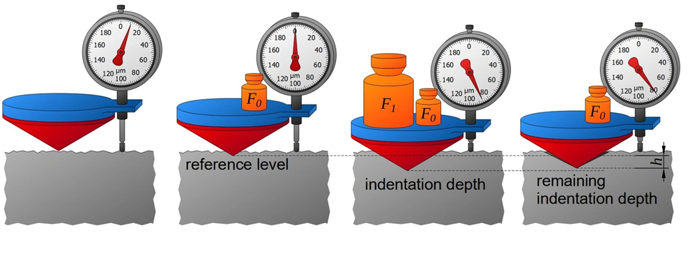
Hardness measurement methods are different in what they measure. The Rockwell hardness test measures the depth of penetration of an indenter into a material under a known load. Brinell and Vickers tests require optical measurement of the indentation size after the testing cycle completes. This difference eliminates the need for secondary dimensional measurement equipment in Rockwell testing. The method gets results within seconds and costs nowhere near as much as optical hardness testers.
The depth-based approach provides additional advantages. Surface finish requirements remain less stringent compared to Vickers or Brinell methods, which demand polished surfaces for accurate optical measurement. Rockwell testing can provide reliable hardness measurements even on surfaces with moderate roughness. This makes it practical for production floor environments where specimen preparation time must remain minimal.
Understanding Load Application: Preliminary (Minor) Load vs. Total (Major) Load
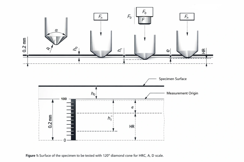
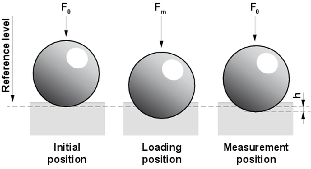
The testing cycle follows a precise sequence whatever the chosen scale. An indenter contacts the specimen surface, and a preliminary force establishes a zero datum position. Regular Rockwell methods use a minor load that equals 10 kgf; superficial Rockwell methods use 3 kgf. The preliminary force is held for a specific dwell time. This allows the indenter to break through surface irregularities and settle.
An additional major load is then applied at a controlled rate. The total force is held for a predetermined period, 7 seconds typically, and elastic recovery stabilizes. The major load is then removed while the preliminary load stays in place. The permanent depth increase (h) between the first measurement under minor load and the second measurement after major load removal determines the hardness value.
The calculation formula varies by scale type:
• Regular Rockwell Scales (HRC/HRB): HR = 130 – (h / 0.002)
• Superficial Rockwell Scales (HR15N/30T): HR = 100 – (h / 0.001)
Each point of hardness on the regular scale represents a 0.002 mm depth variation, while superficial scales measure 0.001 mm increments.
Decoding Rockwell Scales: Choosing Between HRC, HRB, HRF, and Superficial Scales
ASTM defines thirty different Rockwell scales through combinations of indenter type and applied force levels. Regular Rockwell scales employ a 10 kgf preliminary force with major loads of 60, 100, or 150 kgf. Superficial scales use a 3 kgf preliminary force with major loads of 15, 30, or 45 kgf.
The HRC scale applies a 150 kgf major load through a diamond cone indenter. This makes it suitable for hardened steel, titanium, and heat-treated materials. HRB uses a 1/16-inch ball indenter with 100 kgf major load for copper alloys and soft steels. HRA serves thin, shallow case-hardened parts with a 60 kgf diamond load. HRF addresses annealed copper and thin soft sheet metals using a 1/16-inch ball at 60 kgf.
Specimen thickness dictates scale selection. Diamond indenter scales need minimum thickness that must reach 10 times the permanent indentation depth; ball indenter scales require 15 times. Selecting the highest feasible load minimizes surface treatment influence and reduces metallographic structure effects on results.
Standard Rockwell Testing Methods and Step-by-Step Procedures
Specimen Surface Preparation: Eliminating Scale, Decarburization, and Roughness
Proper execution of the rockwell hardness test begins with surface preparation matched to the selected scale. Regular Rockwell scales tolerate a ground surface finish of 0.8 μm Ra or better, which you can achieve with 600 grit abrasive. But as test forces decrease, surface requirements intensify. The 15 kgf superficial scales just need polished or lapped surfaces to prevent indenter slippage and false readings. Excessive grinding pressure during preparation generates frictional heat that alters surface metallurgy and compromises result accuracy.
Decarburization presents a distinct challenge in through-hardened steel evaluation. Carbon loss at the surface reduces hardness independent of heat treatment quality. Carbon atoms diffuse outward during furnace processing, and the depleted surface layer exhibits lower stress resistance than the core material. Accurate substrate hardness measurement becomes necessary, so you must grind beneath the oxide and decarburized layer using light pressure with fine wheels. Decarburization depth verification needs microhardness traverses from thread crests toward the core, where hardness drops of 30 Vickers units or more indicate carbon depletion.
Surface-treated components need different approaches. You cannot grind carburized, nitrided, or carbonitrided parts into the case without destroying the treatment zone. Light polishing with fine abrasive paper prepares these surfaces while preserving case integrity. Case depth dictates load selection; shallow cases just need lighter forces to prevent core penetration.
Correct Placement and Execution on Flat vs. Cylindrical/Curved Surfaces
Cylindrical surfaces introduce systematic errors due to reduced lateral material support. The indenter penetrates deeper on convex surfaces and registers lower hardness values than flat specimens of the same material. Diameters exceeding 25 mm provide adequate support structure and eliminate correction requirements. Smaller diameter materials need ASTM correction factors added to test results. Digital rockwell hardness tester units apply these corrections when you enter diameter parameters; manual dial gage instruments need reference to published tables.
Concave surfaces exhibit opposite behavior. Material curves toward the indenter and provides improved support that produces shallower indentation and artificially lifted readings. You must subtract correction factors in these cases. Exact indenter alignment to the radius remains critical during cylindrical testing.
Specimen support eliminates movement-induced errors. One Rockwell point equals 0.002 mm on regular scales, so 0.001 inch of movement generates errors exceeding 10 points. Supporting anvils must match specimen geometry, remain rigid under load, and present the test surface perpendicular to the indenter axis. Both anvil and specimen contact surfaces need cleaning to remove debris, scale, and lubricants before testing.
Identifying Common Testing Errors and How to Achieve Gage Repeatability
Several procedural violations compromise rockwell hardness chart accuracy:
- Insufficient spacing: Indentations need separation of at least three indentation diameters to avoid plastic deformation zones. Edge proximity must exceed 2.5 diameters.
- Inadequate thickness: Specimen thickness below 10 times the indentation depth allows anvil influence. Visible deformation on the opposite surface invalidates results
- Contaminated components: Debris on indenters or anvils introduces point variations. Cleaning with ethyl alcohol and filtered compressed air precedes each test session
Gage repeatability and reproducibility studies confirm instrument performance. Three verification indentations on certified reference materials must fall within the block’s certified hardness range. Values outside this range need debris removal and retesting. If failure persists, you must replace the indenter. Daily verification ensures measurement system stability whatever the setup changes.
Metrology Standards and Compliance: ASTM E18 and ISO 6508
Key Requirements of ASTM E18 (American Standard) for Industrial Metals
ASTM E18 establishes complete procedures for Rockwell hardness testing of metallic materials and covers both regular and superficial hardness test methods. This standard specifies requirements for rockwell hardness tester machines, indenter geometries, test force application and result reporting protocols. Force levels are defined in both SI units (Newtons) and historical kgf units owing to continued industrial usage. The standard is enough for acceptance testing of commercial shipments and has been used widely in North American manufacturing supply chains.
ASTM E18 mandates three distinct verification protocols. Direct verification checks if core machine parameters including applied force, depth measurement and testing cycle timing fall within specified tolerances. This verification is required when purchasing new equipment, following any adjustments or repairs affecting testing variables, or when indirect verification fails. Indirect verification employs calibrated reference hardness blocks to assess measurement accuracy against known hardness values. This method is performed annually, upon machine installation or after relocation. Daily verification precedes each testing session and is required whenever the anvil, test force or indenter changes.
ISO 6508 Guidelines: Ensuring International Quality Consistency
ISO 6508-1:2015 defines methods for both regular and superficial Rockwell hardness testing applicable to stationary and portable testing machine. The standard applies to metallic materials and references tungsten carbide composite as the standard ball indenter material. Steel indenter balls remain permissible only when complying with Annex A specifications.
ISO 6508-2:2015 establishes two verification approaches for rockwell hardness tester equipment. Direct verification determines whether force application, depth measurement and timing parameters meet tolerance requirements. Indirect verification uses calibrated reference blocks to verify measurement capability against materials of known hardness. The indirect method alone is enough for periodic routine service checks.
Machine Calibration, Diamond Indenter Verification and Reference Block Certification
Diamond indenter certification requires verification by accredited laboratories for both geometrical and performance standards per ASTM and ISO requirements. Every indenter receives a compliance certificate that ensures traceability. The conical angle must be controlled to 120° ±0.35° through precision grinding, lapping and hand polishing. Performance testing compares indenters against 0-0 master standards within tight tolerances that accredited laboratories establish.
Reference block calibration follows ISO/IEC 17025 accreditation protocols. Blocks undergo 100% inspection for physical requirements including thickness, flatness, parallelism, surface roughness and magnetism using NIST traceable devices. Each block receives individual certification that provides full traceability. Daily verification requires testing within 15 Rockwell points of the specimen hardness value.
Advanced Applications: Evaluating Hardness in Complex Manufacturing Processes
Image Source: hardnesstests
Heat Treatment Verification: Case Hardening, Through Hardening, and Annealing Profiles
Thermochemical surface treatments just need precise case depth verification to confirm diffusion layer effectiveness. Carburized or carbonitrided parts specify effective case depth (ECD) as the distance from surface to 550 HV hardness limit per EN ISO 2639. Induction or flame-hardened components require measurement to 80% of minimum surface hardness according to EN 10328 and ISO 3754. Nitrided parts follow DIN 50190-3, which defines case depth as the maximum distance where hardness exceeds core hardness by 50 HV. Microhardness traverses executed at regular intervals from edge toward core generate hardness progression graphs. These graphs reveal treatment uniformity. Through-hardened parts exhibit consistent hardness throughout cross-sections. Annealed materials demonstrate reduced hardness values that indicate stress relief and improved machinability.
The Powder Metallurgy Pitfall: Apparent Hardness vs. Matrix Hardness in Sintered Parts (MPIF 35)
Powder metallurgy components present unique measurement challenges due to residual porosity. Apparent hardness represents a composite value influenced by both particle hardness and void content. It functions as a yield strength indicator. Particle hardness (matrix hardness) measures intrinsic metallic hardness unaffected by density. Large-radius indenters can strike pores and register misleadingly low readings. MPIF standards recommend Vickers microhardness testing with diamond pyramid indenters that create small indentations placed within fully dense zones. This approach records true matrix hardness rather than bulk apparent hardness of porous structures.
Microhardness Testing (Vickers) for Thin-Walled MIM Components and Precision Nozzles
Metal injection molding parts require Vickers hardness verification following heat treatment to confirm process effectiveness. Applied load force substantially affects measured values. Lower loads increase recorded Vickers hardness on MIM sample surfaces. Material density directly relates to hardness performance. Parts with density ≥7.4 g/cm³ exhibit lower hardness than traditionally manufactured components at 7.81 g/cm³. Standard Vickers testing employs 200 g loads with 10-second dwell times on polished surfaces. The non-destructive nature preserves finished components while providing quality assessments for thin-walled geometries and precision nozzles. Conventional rockwell hardness test methods would cause through-thickness penetration in these applications.
Comparative Analysis: Rockwell vs. Brinell vs. Vickers
Material Suitability and Load Range Comparison Matrix
Selecting between testing methods requires matching material properties with measurement capabilities. Brinell testing applies forces from 500 to 3000 kgf through hardened steel or carbide balls. This makes it suitable for castings, forgings, and materials with coarse grain structures where large indentations average heterogeneities. Vickers employs a diamond pyramid under loads ranging from 1 to 120 kgf and provides versatility across soft to very hard materials. The rockwell hardness test operates within 15 to 150 kgf load ranges depending on scale selection and positions itself between Brinell’s heavy loads and Vickers’ lighter forces.
Material thickness constraints differ substantially. Brinell requires specimens at least 10 times the indentation depth and limits thin section testing. Vickers measurements prove viable on specimens as thin as 0.15 mm with appropriate load selection. Rockwell testing accommodates intermediate thicknesses based on chosen scale and indenter combination.
Prioritizing Rockwell for High-Volume B2B Production Line Inspection
Production environments favor the rockwell hardness tester for speed and operator simplicity. Direct dial or digital readout eliminates microscopic measurement and reduces cycle time to seconds per test. Brinell and Vickers demand optical measurement of indentation diameters. They require magnification equipment and trained technicians.
Rockwell testing produces minimal surface marking and allows tested parts to proceed through manufacturing without cosmetic rejection. The rockwell hardness chart provides pass/fail decisions against specification limits and simplifies quality control processes in high-volume facilities.
Partner with Us for Quality-Assured Precision Component Manufacturing
Advanced Metallurgical Labs with Automated Digital Testing Infrastructure
Modern precision component manufacturing just needs rigorous hardness verification backed by calibrated equipment. Facilities equipped with Wilson Rockwell 574 testers deliver best-in-class gage repeatability and reproducibility for load ranges from 3 to 150 kgf. The RH2150 model extends testing capacity to 187.5 kgf with built-in USB connectivity for data integration. Vickers and Knoop microhardness systems operating from 0.01 to 2 kgf handle thin-walled metal injection molding components and surface-treated parts that require non-destructive evaluation. Brinell testing capabilities reach 3000 kgf and accommodate castings and forgings with coarse grain structures. Automated optical inspection and CMM verification ensure dimensional accuracy complements metallurgical assessment.
Submit Your Custom Drawings and Hardness Specifications for a Free DFM Review
Design for manufacturability analysis identifies cost-driving features before production begins. Blanket tight tolerances applied to entire prints prove uneconomical and unachievable, especially when you have multi-bend formed parts. Engineering teams review submitted drawings and mark critical-to-function dimensions that require tight control while assigning realistic defaults elsewhere. This one-time optimization reduces manufacturing costs without compromising performance requirements. Submit CAD models with hardness specifications among quote requests to receive manufacturability feedback addressing material selection, heat treatment feasibility and inspection approaches matched to your rockwell hardness test requirements.
Rockwell hardness testing is widely used for production control, incoming material inspection, and heat treatment verification. It’s particularly valuable for evaluating heat-treated steel, case-hardened components, through-hardened parts, and various metal alloys. The method’s speed and direct readout capabilities make it ideal for high-volume quality control in manufacturing environments.
The two primary standards are ASTM E18 for North American applications and ISO 6508 for international compliance. ASTM E18 covers comprehensive procedures for both regular and superficial Rockwell testing of metallic materials, while ISO 6508-1:2015 defines methods applicable to stationary and portable testing machines, ensuring global quality consistency.
ASTM defines thirty different Rockwell scales using combinations of indenter types and load levels. The most common include HRC (150 kgf diamond indenter for hardened steel), HRB (100 kgf ball indenter for softer metals), HRA (60 kgf diamond for thin case-hardened parts), and HRF (60 kgf ball for annealed materials). Superficial scales use lighter loads for thin specimens.
Rockwell measures indentation depth rather than width, eliminating the need for optical measurement equipment. This provides faster results—typically within seconds—compared to Brinell and Vickers methods that require microscopic measurement of indentation diameters. Rockwell also has less stringent surface finish requirements and produces minimal surface marking.
Accurate testing requires proper surface preparation (ground to 0.8 μm Ra or better), adequate specimen thickness (at least 10 times indentation depth), correct indenter and anvil selection, and proper spacing between indentations (minimum three indentation diameters apart). Regular calibration using certified reference blocks and verified diamond indenters ensures measurement reliability.