
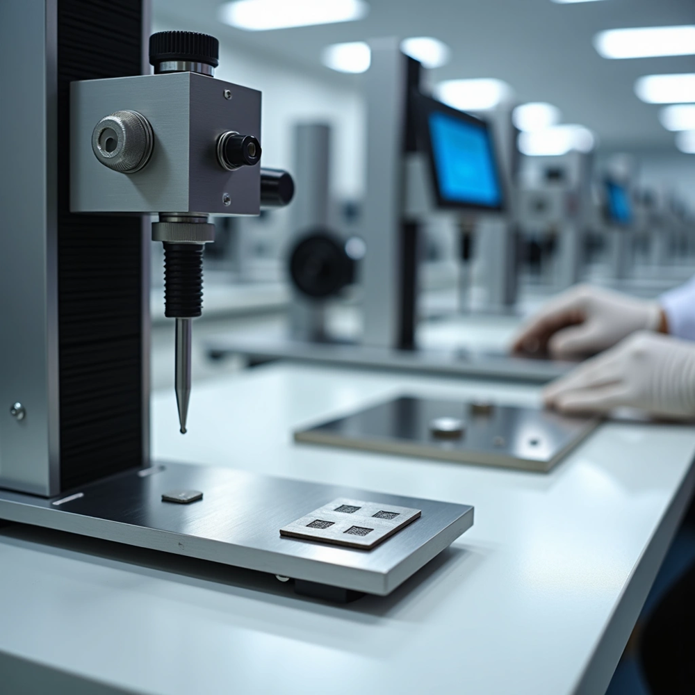
The Vickers hardness test is a universal method for measuring material hardness, from soft metals to ceramics, with diamond sitting at the top of the scale at 10,000 HV. Robert L. Smith and George E. Sandland at Vickers Ltd developed this optical testing method in 1921. It uses a 136° diamond pyramid as an indenter. The test’s versatility is evident in its load range, spanning from 10 gf to 100 kgf. Standardized according to ISO 6507 and ASTM E384, the Vickers hardness tester delivers precise results in micro to macro testing applications. This piece explains how the Vickers test works and breaks down the Vickers hardness test formula. It explores real-life applications in metallurgy, aerospace, automotive and quality control.
What Is the Vickers Hardness Test?
What Does HV Mean?
HV stands for Vickers Hardness, representing the hardness value obtained from the Vickers hardness test. The unit is also known as Vickers Pyramid Number or Diamond Pyramid Hardness (DPH). Obsolete symbols such as DPN (Diamond Pyramid Number) and VPN (Vickers Pyramid Number) were used before the 1960s, but HV became the standard symbol per ASTM E2 and E384.
History of the Vickers Hardness Test
Robert L. Smith and George E. Sandland developed the Vickers hardness test in 1921 at Vickers Ltd, a British engineering conglomerate. The test emerged as an alternative to the Brinell method and addressed material limitations that restricted the Brinell method’s effectiveness. Smith and Sandland used a pyramid-shaped diamond rather than a ball indenter. This resulted in a more consistent and versatile hardness measurement system.
Why People Use the Vickers Method
The Vickers test accommodates all metals and materials, whatever their hardness, from very soft (HV 1) to very hard substances (HV 3000). The same diamond indenter works for all test loads, unlike other methods. This eliminates the need for retooling. Vickers indentations at different loads have geometric similarity and produce constant HV values across a wide test range, as long as the specimen remains reasonably homogeneous.
How the Diamond Pyramid Indenter Works
The indenter consists of a square-based diamond pyramid with opposite faces meeting at 136°. This specific angle originated from Brinell test observations, where the ideal impression measured 3/8 of the ball’s diameter. Two tangents to a circle at chord ends of 3/8 diameter intersect at 136°. This establishes the optimal included angle. Experimental testing confirmed that hardness values remained constant on homogeneous materials, whatever the applied load.
How Does the Vickers Hardness Test Work?
Sample Preparation
Surface quality depends on the applied load. Macro hardness testing with loads above 1 kgf just needs ground surfaces, while microhardness testing at or below 1 kgf just needs mechanically polished or electropolished surfaces. The specimen surface must sit perpendicular to the indenter. Samples mount in plastic medium to aid preparation and testing.
Applying the Test Load
Test force increases from zero to its final value within 2 to 8 seconds, with 7 seconds as the nominal duration. The diamond indenter presses smoothly into the test surface without impact. Load holds for 10 to 15 seconds before full unloading occurs. Dwell time that exceeds this range needs specification in the hardness value notation.
Measuring the Indentation
Both diagonals of the square impression receive measurement using an optical microscope. Vickers indents form perfect squares in rare cases. Operators measure both diagonals to the nearest 0.1 µm and calculate the average. Standards mandate a minimum diagonal width of 20 µm for accurate readings.
Calculating Hardness Values
Hardness value equals applied force divided by the indentation’s surface area. Larger measured diagonals indicate softer materials.
Understanding HV Notation
Results appear as xxxHVyy or xxxHVyy/zz. Here xxx represents the hardness number and yy shows the test load in kgf. The zz indicates dwell time in seconds when it differs from standard duration.
Vickers Hardness Formula Explained
HV = 1.8544F / d²
The Vickers hardness test formula calculates hardness by dividing applied force by the indentation’s surface area: HV = 1.8544F / d². The constant 1.8544 comes from the geometric relationship A = d²/(2sin(136°/2)), which simplifies to A ≈ d²/1.8544. This mathematical relationship stems from the 136° apex angle of the diamond pyramid indenter.
Variables in the Formula
F represents the test force measured in kilogram-force (kgf). The variable d indicates the average length of both diagonals in millimeters. The formula produces values in kgf/mm². Standard practice reports Vickers hardness as dimensionless numbers. Converting to SI units needs different constants: HV ≈ 0.1891F/d² when F is in Newtons and d is in millimeters.
Example Vickers Hardness Calculation
The diagonal lengths receive optical measurement after load removal. A material with 100 HV hardness equals around 980.7 MPa.
Factors Affecting Accuracy
You need to control external factors like vibrations and temperature during testing. The indenter must remain perpendicular to the tested surface. Standards prescribe a minimum diagonal width of 20 µm to ensure accurate readings. The tester needs recalibration every time the indenter or objective lens changes.
Vickers Hardness Chart and Material Values
Vickers Hardness Scale Overview
Material hardness spans from soft metals near 5 HV to diamond at 10,000 HV. Tin registers at 5 HV. Tungsten carbide and alumina reach 2,500 HV. This wide range demonstrates why the Vickers method accommodates all metals and many non-metallic materials.
Vickers Hardness of Carbon Steel
Carbon steel exhibits 55 to 120 HV5, with test loads of 5 kgf. Mild steel falls within 140 to 280 HV. Martensite, a hardened steel microstructure, achieves 1,000 HV.
Vickers Hardness of Stainless Steel
316L stainless steel measures 140 HV30. 347L grades reach 180 HV30. Ferritic types range from 170 to 300 HV, and austenitic grades span 180 to 400 HV. Martensitic stainless steel delivers 450 to 800 HV.
Vickers Hardness of Titanium Alloys
Titanium alloys undergo heat treatment evaluation through Vickers testing. Specific values vary based on alloy composition and thermal processing conditions.
Vickers Hardness of Aluminum Alloys
Aluminum alloys measure 25 to 140 HV. Pure aluminum registers 20 to 30 HV. 7075-T6 alloy achieves 150 to 170 HV.
Vickers Hardness of Ceramics
Ceramics exceed 1,000 HV and may approach 2,000 HV due to material composition. Silicon nitride reaches 750 HV, and zirconia measures 1,300 HV. Quartz registers 1,200 HV.
Vickers Hardness of Powder Metallurgy Parts
Powder metallurgy components require low test forces for small particle sizes below 0.1 mm. Aluminum powder shows 25 to 35 HV.
| Material | Typical HV |
|---|---|
| Iron | 80-150 |
| Carbon Steel | 120-400 |
| Stainless Steel 316L | 140-220 |
| Stainless Steel 17-4PH | 300-450 |
| Titanium Ti-6Al-4V | 320-380 |
| Alumina Ceramic | 1500-2000 |
| Zirconia Ceramic | 1200-1400 |
| Tungsten Carbide | 1500-2400 |
Vickers Hardness Conversion Chart
HV to HRC Conversion
Converting Vickers to Rockwell C scale follows reference tables that have been around for decades. A steel sample measuring 262 HV converts to approximately 27 HRC. Similarly, 300 HV corresponds to roughly 30.9 HRC. For harder materials, 500 HV translates to 49.7 HRC, while 700 HV reaches 58.5 HRC. We apply these conversions to steels and related alloys.
HV to HB Conversion
Brinell hardness values match closely with Vickers measurements in overlapping ranges. A material at 300 HB equals approximately 303 HV. Likewise, 200 HB converts to 190 HV, and 400 HB corresponds to 380 HV. The relationship remains consistent across medium hardness ranges.
When Hardness Conversion Is Reliable
All conversions between hardness scales are approximate rather than exact equivalents. ASTM E140 provides standardized conversion tables, yet these values derive from testing conducted years ago, sometimes on equipment no longer used. Each testing method reviews different aspects of material behavior under distinct loading conditions. Material composition, heat treatment history, and grain structure greatly affect conversion accuracy. You should use the correct hardness test method whenever possible. Operators must document the original measurement and conversion method used if conversions become necessary.
Micro Vickers Hardness Testing
What Is Micro Vickers Hardness?
Microhardness testing refers to Vickers measurements performed with loads below 0.2 kgf. According to ISO 6507, the micro range uses forces under 1,000g (10N). This distinguishes it from small load testing (0.2 to 5 kgf) and macro range applications (≥ 5 kgf). This specialized technique assesses hardness on microscopic samples, thin coatings, individual material phases and surface treatments.
HV0.01 to HV1 Explained
Micro Vickers notation indicates the applied test force. HV 0.01 uses 0.098 N, HV 0.025 applies 0.245 N, HV 0.05 employs 0.490 N, and HV 0.1 requires 0.980 N. The microhardness range spans from HV 0.01 to HV 1 and covers structural components and very thin layers. Specimens must be at least 1.5 times thicker than the indentation diagonal. Minimum thicknesses range between 0.085 mm and 6.5 mm depending on load.
Thin Coatings and Surface Layers
Microhardness testing assesses thin film coatings by measuring hardness perpendicular to the surface on prepared cross-sections. Indentations should measure 20 microns or greater on the diagonal to minimize optical measurement variability. Testing chrome and nickel coatings determines impact and wear resistance in rotational and reciprocal applications.
Case Hardness Depth Testing
Cross-sectioned samples receive a series of microhardness impressions from the edge toward the center. This creates a hardness progression profile. This method identifies case-hardened layer depths, decarburization, carburization, and grind burns.
Applications of the Vickers Hardness Test
Heat-Treated Components
One main use of the Vickers hardness tester is to verify heat treatment effectiveness. The method measures hardness changes before and after thermal processing and confirms proper tempering or quenching results. Cross-sectional hardness profiles evaluate carburized and nitrided surface layers. The test detects decarburization and case depth variations that indicate processing inconsistencies.
Powder Metallurgy Components
Sintered metals undergo testing using HV5, HV10, and HV20 load ranges as standard practice. Powder particle evaluation requires specialized preparation. Embedding particles in resin before polishing creates suitable test surfaces. The Vickers test identifies contamination effects on compressibility and reveals microstructural variations between particle size fractions.
Metal Injection Molding (MIM)
MIM components receive hardness testing under 200g loads with 10-second dwell times. The test verifies density-hardness relationships, as parts with lower density measure less hardness than traditionally manufactured equivalents. MIM parts achieve hardness values up to 700 HV and confirm material homogeneity throughout complex geometries.
Aerospace Materials
Turbine blades, structural components, and landing gear materials undergo Vickers testing to meet stringent safety standards. Jet engine coatings and thin metal components require microhardness testing for quality verification. The method assesses titanium implant hardness in medical aerospace uses.
Automotive Gears and Shafts
Engine components including crankshafts, camshafts, and pistons receive hardness evaluation. Transmission gears require testing to prevent premature wear and ensure smooth operation. Chassis materials undergo assessment for structural integrity under dynamic loads.
Electronics and Coatings
Semiconductor materials, connector components, and PCB substrates receive Vickers testing. Solder joint hardness measurements ensure reliability in micro-components. Surface coatings undergo evaluation for wear resistance and durability in different uses.
Advantages of the Vickers Hardness Test
High Accuracy
The diamond indenter’s small and symmetrical shape produces well-defined indents and ensures precise measurements. Calculations remain independent of indenter size and make results reliable across different materials and test conditions. This consistency stems from the geometric properties of the 136° pyramid angle, which maintains measurement accuracy whatever the specimen hardness.
Wide Load Range
Testing loads span from 10 gf to 100 kgf and accommodate both microhardness and macrohardness applications. This flexibility allows operators to select appropriate forces based on specimen thickness, material properties and testing objectives. The same indenter works across all load ranges and eliminates retooling requirements between tests.
Suitable for Hard and Soft Materials
The Vickers test covers hardness values from very soft materials at HV 1 to very hard substances reaching HV 1200. Both ceramics and plastics receive evaluation using similar equipment and methodology. The test’s universal applicability eliminates the need for multiple hardness testing systems in quality control laboratories.
Ideal to Test Small Components
Small indentation sizes enable nearly non-destructive testing and allow specimens to remain usable after evaluation. Microhardness testing capabilities assess thin films and coatings with precision. Low loads create minimal surface disruption, which makes the method suitable to test precision components where material removal or deformation poses concerns.
Limitations of the Vickers Hardness Test
Time-Consuming
Test cycles require 30 to 60 seconds per measurement, excluding specimen preparation time. Optical measurement and calculation procedures extend testing duration beyond faster methods like Rockwell testing. Production environments with high throughput requirements find the Vickers test impractical for routine quality checks.
Requires Surface Preparation
Optical indent evaluation demands excellent surface quality. Test locations need grinding and polishing. Precise evaluation becomes difficult without proper preparation. Rough or curved surfaces produce inaccurate readings. Flat specimens with polished surfaces are essential for high-accuracy measurements, and quality requirements intensify as force decreases. The indentation’s perimeter and depth must appear clearly defined under microscope observation.
Optical Measurement Errors
Diagonal length measurement through optical methods introduces potential errors, especially when you have low load force testing. Poor lighting, incorrect microscope focusing and human error in reading measurement scales affect accuracy. Surface roughness, material inhomogeneities and crack formation around indentations compromise measurement precision. Manual reading introduces subjectivity. Two operators may place measuring lines differently on small indents.
Higher Equipment Cost
Vickers hardness testers cost more than Rockwell testers because they require optical systems for indent evaluation. Equipment expenses increase further with advanced features for automated measurement and analysis.
Vickers vs Other Hardness Tests
Vickers vs Rockwell
Rockwell testing measures residual indentation depth. The Vickers method assesses the diagonal length of the impression. Rockwell applies loads between a few kilograms and several thousand kilograms. Vickers uses smaller forces that range from a few grams to a few hundred grams. The Rockwell test produces conical impressions and delivers results fast. This makes it suitable for rapid batch testing. Vickers testing requires optical measurement of diamond-shaped indentations and extends the test duration. Rockwell suits production environments and metal engineering materials. Vickers serves hard materials that include ceramics and glass.
Vickers vs Brinell
Brinell testing accommodates larger samples and coarse microstructures with a tungsten carbide ball indenter. The method tolerates rough surfaces better than Vickers does. Vickers demands polished specimens for accurate diagonal measurement. Vickers delivers superior precision through finer indentations. This makes it preferable for laboratory and research applications.
Vickers vs Knoop
Knoop indenters penetrate specimens half as deep as Vickers indenters under similar loads. This shallow penetration suits very thin layers such as aluminum foil. Knoop produces elongated indentations that are ideal for small, longish specimens. Vickers creates square impressions better suited for rounded samples. Knoop testing prevents cracking in brittle materials like glass and ceramics. Knoop standardization extends to HK 2. Vickers covers the full hardness range.
Which Hardness Test Is Best?
Material characteristics, component dimensions and required precision determine the selection between methods. Rockwell serves routine production quality checks when speed matters. Vickers and Knoop address thin coatings, microstructures and applications that require high-resolution measurements.
Conclusion
The Vickers hardness test is a universal measurement method. It accommodates materials from soft metals to hard ceramics with exceptional precision. This piece covered the testing methodology and explained the HV = 1.8544F/d² formula. We explored applications in aerospace and automotive industries. The method’s versatility stems from its wide load range and consistent diamond indenter geometry. The Vickers test remains critical for quality control, heat treatment verification, and material characterization in modern manufacturing environments that demand accuracy.
FAQs
Q1. What is the Vickers hardness test used for? The Vickers hardness test is used for measuring the hardness of various materials, from soft metals to hard ceramics. It’s particularly useful for testing thin materials like foils, small components, individual microstructures, surface layers, and measuring case hardening depth. The test creates very small indentations, making it ideal for precision applications in aerospace, automotive, powder metallurgy, and quality control environments.
Q2. How do you calculate Vickers hardness? Vickers hardness is calculated using the formula HV = 1.8544F/d², where F represents the applied force in kilogram-force (kgf) and d is the average length of both diagonals of the square indentation in millimeters. The constant 1.8544 derives from the geometric relationship of the 136° diamond pyramid indenter. The result represents the applied force divided by the surface area of the indentation.
Q3. How is Vickers hardness reported? Vickers hardness values are reported in the format xxxHVyy, where xxx is the hardness number, HV indicates the Vickers scale, and yy shows the test load in kilogram-force. For example, 440HV30 means a hardness of 440 using a 30 kgf load. If the dwell time differs from the standard 10-15 seconds, it’s noted as xxxHVyy/zz, where zz represents the duration in seconds.
Q4. What materials can be tested with the Vickers hardness test? The Vickers test can measure hardness across an extremely wide range of materials, from very soft metals like tin (5 HV) to extremely hard materials like diamond (10,000 HV). It works effectively on carbon steel, stainless steel, titanium alloys, aluminum alloys, ceramics, powder metallurgy parts, and even plastics. This universal applicability makes it suitable for virtually all metals and many non-metallic materials.
Q5. What are the main advantages of the Vickers hardness test? The Vickers test offers high accuracy due to its well-defined diamond indentations, works across a wide load range from 10 gf to 100 kgf, and uses the same indenter for all materials and loads. It’s suitable for both hard and soft materials, ideal for small components due to minimal surface disruption, and provides consistent results regardless of specimen hardness. The small indentation size makes it virtually non-destructive.