Metal Injection Molding (MIM) emerges as the optimal manufacturing solution for humanoid robot gears, addressing the critical challenge of achieving high torque density while maintaining compact, lightweight joint designs for the projected $6+ billion robotics market.
• MIM delivers unmatched geometric freedom, creating complex integrated gear-shaft assemblies with 0.5-1.0mm wall thickness that traditional CNC machining cannot achieve economically.
• Material efficiency reaches 97% versus CNC’s 30%, with specialized alloys like 8620 steel and 17-4PH providing optimal strength-to-weight ratios for robotic joint applications.
• Precision tolerances of ±0.3-0.5% enable micro-planetary gear systems while managing 15-20% sintering shrinkage through advanced moldflow analysis and compensated tooling.
• Rapid scaling from prototype to million-unit production shortens development cycles for robot startups targeting 2026 mass production deadlines with bridge tooling delivering parts in 4-6 weeks.
• Zero-backlash performance through topology optimization reduces gear mass by 25-30% while integrating bearings and keyways directly into gear geometry for space-saving designs.
The convergence of MIM’s manufacturing capabilities with robotics’ demanding performance requirements positions this technology as the foundation for next-generation humanoid robot joint systems, enabling the transition from laboratory prototypes to commercial-scale production. 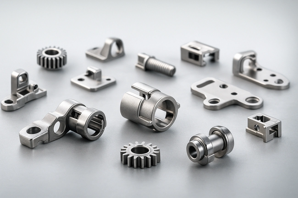 Humanoid robots represent a projected $6+ billion opportunity within the next 10 to 15 years, yet building machines that move like humans demands solving a critical electromechanical engineering challenge. Each humanoid can incorporate 40 or more different joints. Each joint must deliver high torque density to support body weight while maintaining minimal size and weight. Metal Injection Molding (MIM) has emerged as a transformative manufacturing approach for producing precision gears that meet these demands. This piece explores what electromechanical systems engineering technology enables through MIM, specifically to explore how geometric freedom, material optimization, and advanced manufacturing processes create gears that balance strength with miniaturization for next-generation robotic joints.
Why MIM is the “Golden Mean” for Robotic Gears
Metal Injection Molding occupies a unique position in gear manufacturing for electromechanical systems engineering technology. It combines attributes that traditional machining and conventional powder metallurgy cannot match on their own.
Geometric Freedom: Creating complex tooth profiles and integrated structures (e.g., gears with shafts/cams) in one piece
MIM enables internal gear teeth, cross-holes, undercuts, and threaded features to be molded directly without secondary operations. Wall thickness can reach down to 0.2mm in complex components. Traditional machining doesn’t deal very well with such thin sections. The process allows gear-shaft integration, stepped gears with differing modules, and eccentric gears where ensuring shaft accuracy would otherwise be difficult. Internal gears can be manufactured right to the bottom, which makes casing mass production possible. Modules of 0.5 or less can be produced successfully with tight tolerance requirements.
MIM vs. Traditional Methods: A comparative analysis (CNC Hobbing, Powder Metallurgy, and Investment Casting)
CNC machining wastes 30-60% of material through subtractive processes. MIM achieves 95-97% material efficiency. The process produces parts 25% to 65% less expensive than conventional production processes. MIM breaks even at 10,000 units versus CNC and 50,000 versus casting for complex geometries. Investment casting cannot match MIM in filling thin sections, surface finish quality, or accurate detail reproduction. Traditional powder metallurgy uses larger powder sizes and uniaxial pressing. This limits three-dimensional complexity that MIM’s feedstock injection makes possible.
Material Versatility: Beyond stainless steel—utilizing high-strength alloy steels and magnetic materials
The process accommodates stainless steels (17-4PH for strength, 316L for corrosion resistance, 420 and 440C for hardness) and low-alloy steels including 4000 series and 52100 for high wear resistance. Magnetic materials include Fe-3%Si for low core losses and Fe-50%Ni for high permeability.
Scalability for Global Production: Transitioning from R&D prototypes to million-unit batches for the 2026 robot market
Affordable series production begins from 5,000 units per year. Production quantities exceeding 5,000-10,000 units annually make MIM economically viable. The technology makes mass production of internal and helical gears possible in volumes reaching one million units per month. Nabtesco plans to double precision gearbox production capacity to two million units per year by 2026, which reflects the robotics market’s scaling demands.
Engineering for High Torque Density in Robotic Joints
Robotic joint design requires matching gear performance to biomechanical load profiles that vary across the kinematic chain.
Specific Demands by Joint Type: High-load joints (Hip/Knee) vs. high-precision joints (Wrists/Hands)
Hip and knee joints endure average walking forces of 1800N with peak loads reaching 3900N during normal gait. Stair climbing generates forces up to 4200N. Stumbling events produce extreme loads of 11000N. Wrist joints operate at lower forces but just need precision, with maximum flexion torques between 8.3 and 11.9 Nm depending on forearm position and extension torques of 4.5 to 6.5 Nm.
Material Hardness vs. Core Toughness: 8620 alloy steel and 17-4PH with specialized heat treatments for impact resistance
8620 alloy steel achieves surface hardness exceeding HRC 60 after carburizing while maintaining core toughness that absorbs shock loads without fracture. 17-4PH stainless steel provides flexibility through precipitation hardening. H900 condition delivers HRC 44-47 for maximum strength and H1025 provides balanced properties at HRC 38-42.
Tooth Profile Optimization: Maximum load distribution to prevent tooth shear under peak torque
Optimized filet profiles reduce bending stress concentrations at the tooth root and enable finer pitch gears with higher contact ratios. Profile modifications prevent localized stress accumulation that initiates tooth shear under shock loads.
NVH (Noise, Vibration, Harshness) Control: MIM’s superior surface finish results in quieter robot operation in indoor environments
MIM components require tighter manufacturing tolerances for electric drive applications. 100% NVH testing identifies micro-geometry errors invisible to traditional inspection methods.
Miniaturization Strategies: Thin Walls and Weight Reduction
Reducing gear mass without sacrificing mechanical performance requires material distribution at extremes that traditional manufacturing cannot achieve.
Wall Thickness at the Limit: Stable 0.5mm – 1.0mm sections that preserve structural integrity
MIM’s optimal wall thickness range spans 0.5-6mm. Thin-wall applications target 0.5-1.5mm for housings and brackets. Standard MIM produces stable sections at 0.3-0.4mm, though this increases green part breakage risk by 10-18% and adds a 30-50% cost premium. Micro-MIM expands capabilities to 0.2-0.25mm using ultra-fine powder.
Topology Optimization: MIM realizes hollow-core gears and lightweight web structures that CNC can’t reach
Hollow gears cut mass while keeping structural integrity. Topology optimization algorithms achieve 25-30% weight reduction in gear housing elements. A practical example shows the advantage: converting a solid boss design to a hollow core with radial ribs cuts mass by 53% and accelerates debinding by 75%.
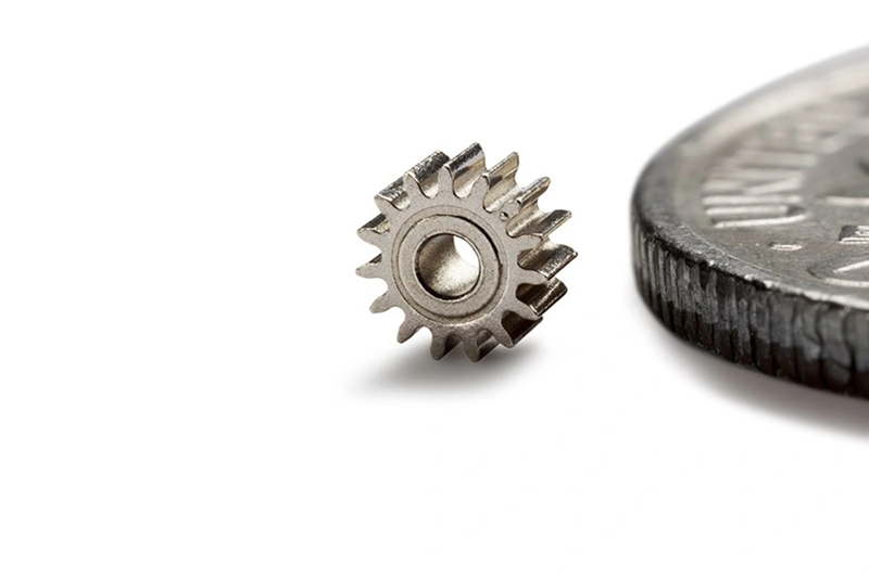
Accuracy in the Small Scale: ±0.3% ~ 0.5% dimensional tolerances for micro-planetary gear systems
MIM holds ±0.3% to ±0.5% tolerances relative to part dimensions and achieves micron-level precision. Miniature gear production reaches diameters as small as 0.05″ with tolerances to 0.0001″.
Space-Saving Designs: Bearings or keyways built directly into the gear geometry cut the total part count
Compact spur gear reductions build bearing and shaft proportions directly into gear mesh parameters. This eliminates separate components.
Manufacturing Excellence and Quality Assurance at JHMIM
Quality assurance in electromechanical systems engineering technology begins at the design simulation stage and extends through final validation protocols.
Advanced Moldflow Analysis: Preventing weld lines at the gear root (the most common point of failure)
Weld lines form when two or more flow fronts meet during mold filling. These locations represent weaker areas where polymer chains may not fuse adequately and result in reduced mechanical strength. Fiber-reinforced materials experience disrupted fiber orientation at weld lines. Fibers become misaligned or cross-oriented and weaken the interface further. Gear root failures occur most often at weld line locations. Higher melt temperature and increased pressure at the weld line promote molecular entanglement that can lead to stronger performance.
Precision Sintering Profiles: Managing 15-20% shrinkage while ensuring gear involute accuracy
Sintering shrinkage reaches 15-20% in MIM processes. Stainless steel parts without secondary sizing achieve dimensional tolerances of ±0.3% to ±0.5% of nominal dimension. Compensated tooling and dedicated inspection protocols enable gear producers to maintain involute accuracy despite substantial volume reduction during sintering.
Secondary Operations for “Zero-Backlash”: When to use precision grinding or PVD coatings for ultra-smooth motion
Zero-backlash mechanisms eliminate play between gear teeth through preloaded spring systems or split gear designs. PVD coatings increase surface hardness and reduce friction while maintaining sharp edges without affecting tool geometry. Surface densification creates pore-free tooth surfaces with mirror-like finish. This reduces noise and improves wear resistance.
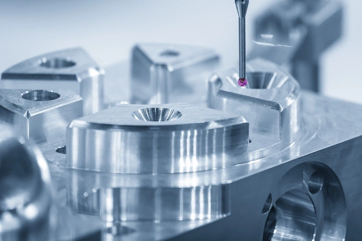
Performance Validation: Hardness testing, torque-to-failure analysis, and coordinate measuring machine (CMM) inspection
Torque-to-failure testing determines the maximum torque a joint can withstand before failure occurs through stripping, shearing, or material breaking. CMMs equipped with rotary tables and gear-checking software cost about half that of dedicated gear inspection equipment. CMM inspection verifies involute accuracy and pitch deviation with deviations kept below 10 μm.
The Future of Robotics Supply Chain
Robot manufacturers face compressed development timelines as production targets escalate toward 2026. Tesla wants mass Optimus production by late 2026, while UBTECH plans 10,000 units each year by 2027. Booster expects capacity reaching tens of thousands of units with declining unit prices. MIM’s prototyping workflows address these needs.
Rapid Prototyping to Mass Production: How JHMIM shortens the T1-to-Mass Production cycle for robot startups
Bridge tooling delivers functional prototypes in 4-6 weeks for validation testing. Production tools undergo design and build at the same time. This approach proves useful when volumes remain below 1,000 parts during early validation stages. CPK modeling identifies all variable elements from feedstock consistency to molding defects and creates efficient supply chains with faster scaling capability. Automated processes allow production volume control at any scale, especially when you have transitions from low to high volume with limited overhead. You can add cavitation to existing molds with reasonable design adjustments instead of preparing new tooling.
Sustainability in Manufacturing: Reduced material waste compared to subtractive CNC machining
MIM achieves 97% material utilization versus CNC machining’s 30% for complex components. A titanium gear example demonstrates the effect: 50,000 parts at 45g each need 9,000 kg billet for CNC versus 2,400 kg feedstock for MIM. This saves 6,600 kg and USD 200,000-300,000 in material costs alone. Excess feedstock undergoes recycling and reduces material expenses with premium alloys.
Conclusion
MIM technology has become everything in humanoid robotics. It solves the challenge of delivering high torque density within compact joint architectures. Manufacturers race toward 2026 production targets, and this manufacturing process provides geometric freedom and material versatility that traditional methods cannot match. JHMIM’s precision manufacturing capabilities enable robot developers to transition faster from prototype to million-unit production. They achieve superior performance and sustainability outcomes that define next-generation electromechanical systems.
FAQs
Q1. What makes MIM technology ideal for manufacturing robotic gears? MIM (Metal Injection Molding) combines geometric freedom with material efficiency, allowing complex tooth profiles and integrated structures to be created in one piece. It achieves 95-97% material utilization compared to traditional machining methods, while enabling thin wall sections down to 0.5mm and maintaining tight tolerances of ±0.3% to ±0.5%. This makes it perfect for producing high-torque, miniaturized gears required in humanoid robot joints.
Q2. How does MIM compare to traditional gear manufacturing methods like CNC machining? MIM offers significant advantages over CNC machining, including 95-97% material efficiency versus CNC’s 30-60% waste rate. For complex geometries, MIM becomes cost-effective at 10,000 units compared to CNC’s higher break-even point. Additionally, MIM can create intricate internal features, undercuts, and integrated components that would require multiple machining operations or be impossible to produce through traditional methods.
Q3. What materials can be used in MIM for robotic gear production? MIM accommodates a wide range of materials beyond stainless steel, including high-strength alloy steels like 8620 (which achieves surface hardness exceeding HRC 60 after carburizing) and 17-4PH stainless steel for corrosion resistance. The process also supports low-alloy steels such as 52100 for wear resistance and magnetic materials like Fe-3%Si and Fe-50%Ni for specialized applications.
Q4. How thin can gear walls be manufactured using MIM technology? MIM can produce stable wall sections in the optimal range of 0.5-6mm, with thin-wall applications typically targeting 0.5-1.5mm. Standard MIM achieves stable sections at 0.3-0.4mm, while advanced micro-MIM techniques can reach as thin as 0.2-0.25mm using ultra-fine powder, enabling significant weight reduction without compromising structural integrity.
Q5. What quality control measures ensure MIM gears meet robotic performance requirements? Quality assurance includes advanced moldflow analysis to prevent weld lines at critical stress points, precision sintering profiles to manage 15-20% shrinkage while maintaining involute accuracy, and comprehensive performance validation through hardness testing, torque-to-failure analysis, and CMM (Coordinate Measuring Machine) inspection. Secondary operations like precision grinding or PVD coatings can be applied when zero-backlash performance is required.