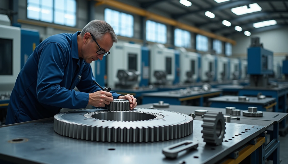
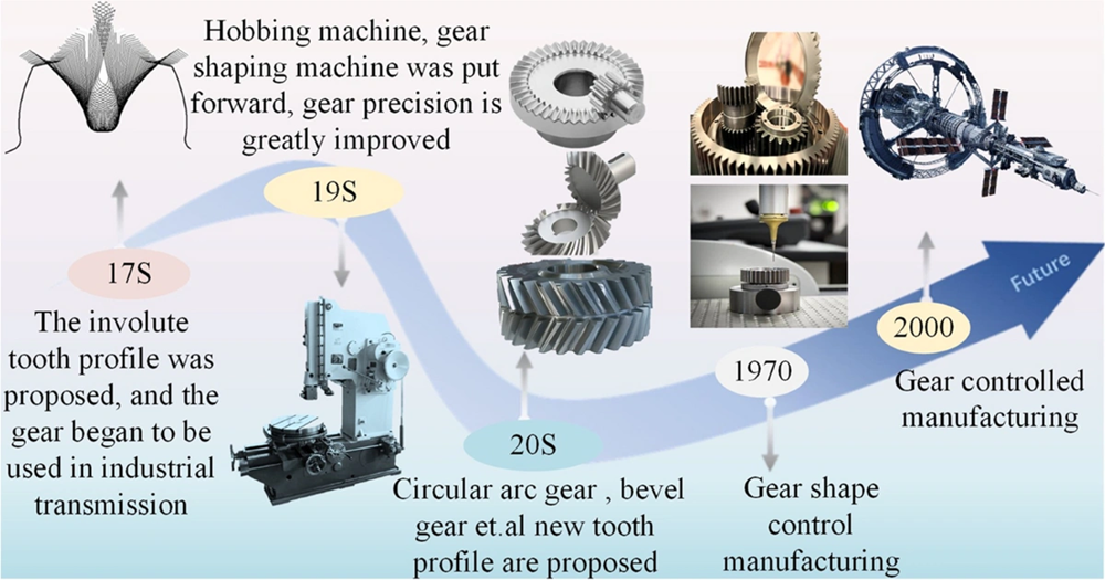
Precision gear manufacture plays a vital role in modern machinery today. Gears serve as mechanical components that power everything from tiny watches to massive automobiles, and they transmit motion and energy effectively . The original wooden components have evolved into sophisticated manufactured parts through technological progress over time.
Gear manufacturing requires exceptional precision since this specialized field works with tight tolerances. These mechanical components serve multiple critical functions in machines and assemblies. They reverse rotational direction, change angular orientation, turn rotary motion into linear movement, and adjust speed and power transmission ratios. The industry rates gear quality based on standards like DIN 3962, which measures and grades different parameters on a scale of 1-12. A manufacturer’s choice of gear production process depends on the gear type, materials used, and specific applications. This piece explores everything in precision gear production – from choosing materials to applying finishing techniques that maximize performance.
Types of Gears and Their Manufacturing Implications
Each type of gear comes with its own manufacturing challenges. You need specific manufacturing methods to get the best performance from different configurations. These differences help manufacturers choose the right production methods for various applications.
Spur Gears: Simplest to Manufacture
Spur gears are the most accessible and straightforward gear configuration in power transmission systems. These cylindrical gears have teeth cut parallel to the shaft, which makes them easier to manufacture. Spur gears give the highest accuracy through simple production processes compared to other gear types. The traditional form milling method uses a cutter that moves along the tooth length at the right depth. The cutter pulls back after cutting each tooth, and the blank rotates until all teeth are complete.
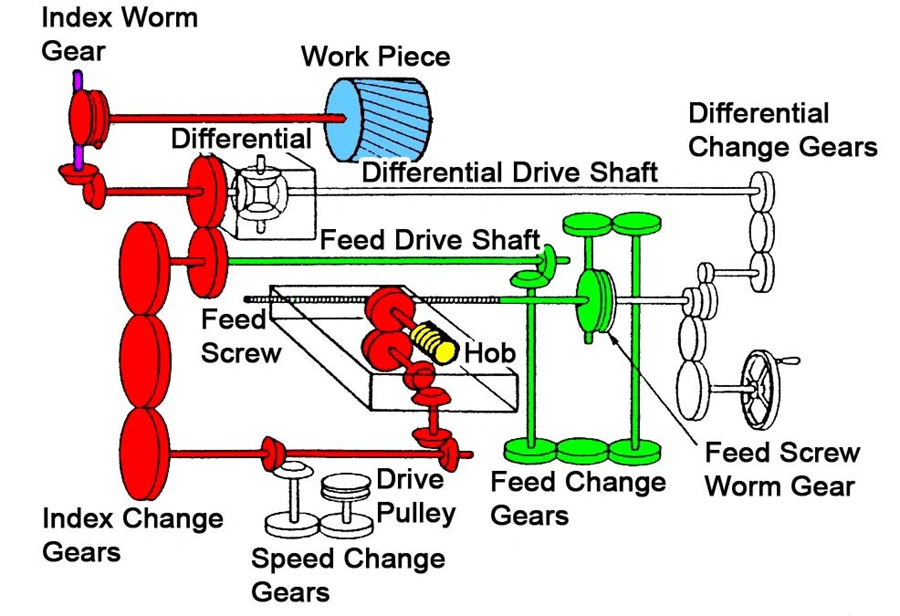
Hobbing works best for mass production. The gear blank and hob—a specialized multi-toothed cutting tool—rotate together in perfect sync. This lets the hob cut the teeth step by step to create the right shape. Spur gears are simple to make, but they can be noisy under heavy loads because of their tooth design.
Helical Gears: Precision and Tolerance Challenges
Helical gears have teeth that spiral around the gear instead of running straight. This design is harder to manufacture but works better in many ways. These gears mesh more smoothly, run more quietly, and handle bigger loads than spur gears. That’s why they work so well in high-speed applications.
The biggest manufacturing challenge comes from their complex tooth shape. The angled teeth make the contact line longer for any given gear width, which spreads the load across more surface area. But this design creates axial thrust forces when running, so you need thrust bearings. Manufacturers use gear hobbing and CNC machining to make these gears, and they must pay special attention to helix angles and tooth profiles.
Bevel Gears: Conical Geometry Considerations
Bevel gears are tough to manufacture because of their cone shape, which helps transmit force between crossing shafts. The complex tooth geometry makes things even harder, especially for spiral and hypoid types. The manufacturing quality directly affects how well the gear works, how it handles loads, and how much noise it makes.
Manufacturers use form cutting, precision forging, and CNC machining to make bevel gears. Technical drawings are the foundations of manufacturing—every detail counts because missing information leads to production mistakes. These gears also need skilled technicians and special equipment for assembly and alignment. Poor assembly or misalignment leads to inefficiency and early failure.
Worm Gears: Self-locking and Friction Factors
Worm gears use a screw-like worm that meshes with a worm wheel to move power between shafts that don’t meet, usually at 90-degree angles. Unlike other gears that mostly roll against each other, worm gears slide more. This creates lots of heat and makes them less efficient.
Material choice matters a lot—manufacturers usually pair a hardened steel worm with a bronze wheel to reduce friction and wear. Single-enveloping worm wheels have a special throat shape that lets several teeth share the load at once. This design can handle more load and runs more smoothly. Manufacturers use thread millers, thread grinding, and hobbing to make multiple-thread worms.
Rack and Pinion: Linear to Rotational Conversion
Rack and pinion systems turn spinning motion into straight-line motion using a round pinion gear that meshes with a flat toothed rack. The rack works like a gear with an endless radius. Manufacturers use precision forging, gear cutting, and CNC machining to make these systems.
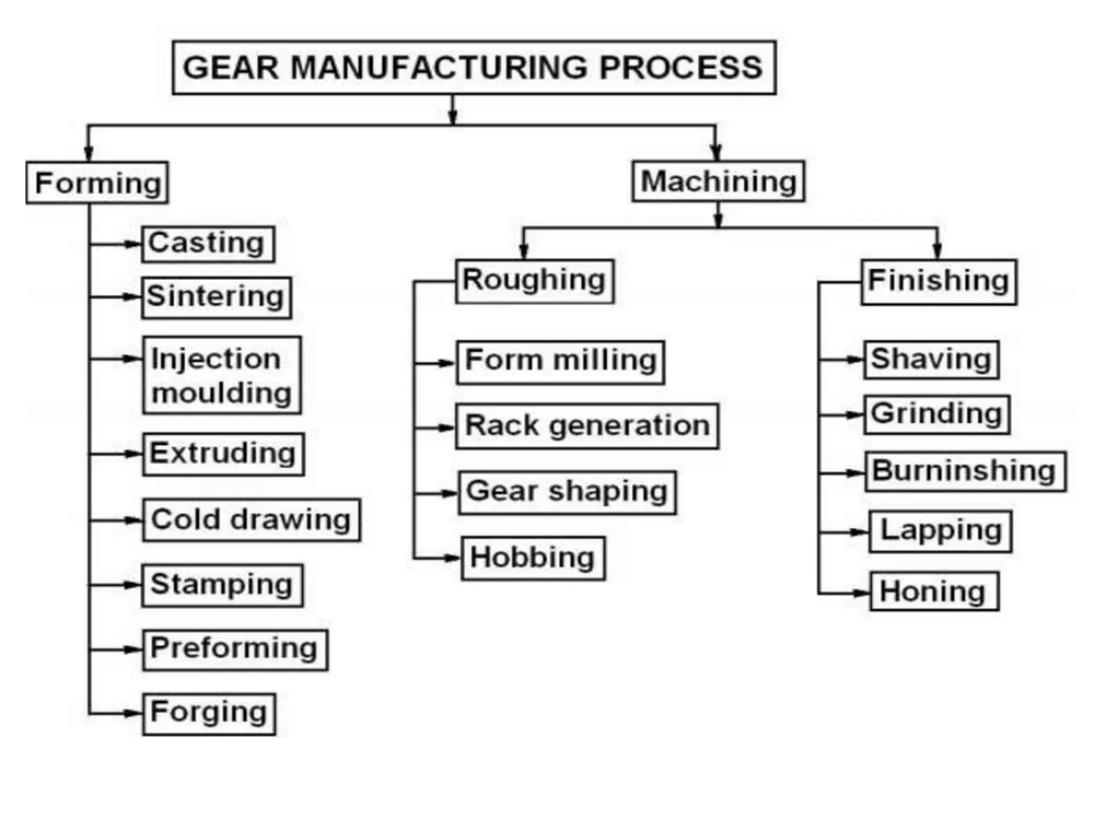
Making these systems takes several careful steps. The process starts with forming the basic shape, then machines cut away material to make the teeth, and finishing touches ensure everything meets quality standards. Manufacturers can form the parts through casting, sintering, injection molding, extruding, cold drawing, or stamping. These systems work great in car steering, stairlifts, railways, and actuators—anywhere you need to change spinning motion into straight-line movement.
Materials Used in Gear Manufacturing
Your choice of materials plays a vital role in gear manufacturing and affects performance, durability, and costs. The materials you pick will determine everything from how much load your gears can handle to how long they’ll last in different uses.
Steel vs Cast Iron: Load and Wear Resistance
Steel tops the list of gear materials because it combines strength, wear resistance, and reasonable costs. Carbon steels work well for most uses, while alloy steels pack extra strength when you need heavy-duty performance. Tool steels with cobalt, molybdenum, tungsten, or vanadium give you better heat resistance and durability – perfect for high-performance gears.
Cast iron shines when it comes to handling compression forces and resists crushing really well. Gray cast iron works great against wear since its graphite flakes act like a built-in lubricant, which makes it perfect when friction is an issue. It also dampens vibrations well, so it’s great for moderate loads at low to medium speeds. The only catch? It’s too brittle for high-impact uses.
Bronze and Plastics: Corrosion and Lightweight Applications
Bronze and brass really stand out when you need corrosion resistance. They work exceptionally well where parts slide against each other or don’t get much lubrication. While not as strong as other options, these materials excel in wet or corrosive environments that would destroy steel.
Nylon and acetal thermoplastics are becoming popular choices for gears that run at low speeds with light torque [4]. Plastic gears weigh five times less than metal ones, run quieter, lubricate themselves, and never rust [1]. You won’t need to stop production for maintenance since these gears don’t need regular lubrication [1].
Material Selection Criteria: Strength, Friction, and Machinability
You’ll need to look at several things when picking gear materials: how much load they’ll carry, speed requirements, where they’ll work, expected lifespan, what they’ll work with, and your budget. High loads call for tough alloy steel, while corrosive settings need stainless steel or the right engineering plastics.
The environment matters too – temperature, humidity, and chemicals can really affect how materials perform. Cost versus benefit also comes into play – sometimes pricier materials pay off through longer life or better reliability.
Powder Metallurgy Materials in Precision Gear Production
Powder metallurgy (PM) gives you a cost-effective way to make gears compared to regular steel or cast iron. You get parts that are almost ready to use with minimal machining, while still meeting tight size requirements. JH MIM brings 20 years of expertise in metal injection molding and powder metallurgy, delivering precision-engineered products worldwide.
PM gears come with some great features: perfect involute tooth profiles, self-lubricating properties through oil absorption, and natural noise reduction from their porous structure. This technology lets you add lightening holes easily and combine gears with other mechanical parts into single components.
Core Gear Manufacturing Processes Explained
Gear manufacture depends on several core processes that transform raw materials into working components. Each manufacturing method works differently based on size, complexity, and how many parts need to be made.
Casting for Large Gear Blanks
Large gear blanks rely heavily on casting, especially when they’re bigger than 6 feet across. Sand casting keeps tooling costs down but isn’t as precise, which makes it perfect for basic applications like cement-mixer barrels and dam gate lifting mechanisms. Die casting gives you a smoother finish and better accuracy, but costs more to set up. This makes it ideal for mass-producing parts used in instruments, washing machines, and small speed reducers. When you need exceptional accuracy with high-temperature materials, investment casting (lost wax process) creates precision gear blanks, though production costs more.
Forging for High Fatigue Resistance
Forging uses compressive force to shape metal alloys into precision gears that have superior mechanical properties. The process heats metal between 1000°C and 1200°C before preforming and finishing forging with precision dies. The process refines the microstructure and lines up grain flow with gear contours. This is a big deal as it means that fatigue strength improves and parts last many more stress cycles before cracks start. Today’s forging achieves precision with tolerances as tight as ±0.05 mm, which means less machining.
Extrusion and Cold Drawing for Smooth Surface Finish
You don’t need to spend much on tools for extrusion and cold drawing, yet these methods work great for making gear-toothed elements. The process pulls (draws) or pushes (extrudes) bars through dies that create the tooth form. Pressure displaces material and creates a work-hardened, remarkably smooth outer surface. Cold drawing is different from extrusion because it happens at room temperature and pulls rather than pushes material through dies. These methods work best with materials that draw well, like high-carbon steels, brass, bronze, and aluminum.
Powder Metallurgy for Small Precision Gears
Powder metallurgy (PM) creates small, precise gears by compacting metal powders at 400-800 MPa and sintering them at around 1120°C. JH MIM brings nearly 20 years of experience to this field. Their factories span more than 18000 square meters with top-tier equipment and 150 skilled workers. PM uses materials efficiently with rates over 95%. These gears offer great benefits: near-net tooth geometry, complex features, self-lubrication capabilities, and sound dampening through controlled porosity.
Machining Methods: Hobbing, Shaping, Broaching, Milling
Gear machining fine-tunes tooth geometry and accuracy after forming. Hobbing stands out as the quickest way to cut teeth. It uses a helical cutting tool that spins continuously with the gear blank until all teeth are done. Power skiving cuts continuously and works several times faster than shaping. It gives you more flexibility than broaching, which helps especially with internal gears. Broaching moves a cutting tool through the gear piece quickly and accurately. While tooling costs more, it produces parts faster than other methods. Custom gears that need precise cutting use milling to remove material tooth by tooth. This gives high precision but takes longer.
Post-Processing Techniques for Gear Finishing
Gear performance improves through finishing operations that modify surfaces with precision to boost durability and operational features. These techniques turn rough-cut gears into precision components ready for tough applications.
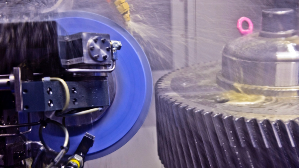
Grinding for Dimensional Accuracy
Gear grinding remains the main finishing method after heat treatment. It removes distortion and delivers exceptional dimensional precision. The process uses abrasive grinding wheels with special profiles to refine tooth shape with high cutting force. Form grinding wheels match exact tooth profiles and process one tooth at a time. Generating grinding uses a grinding worm that meshes with the gear blank in continuous, synchronized rotation. Grinding works on hardened gears to fix thermal distortions and create a better surface finish. This leads to higher-quality gears for engineering applications of all types.
Lapping for High Precision Surfaces
Lapping marks the final finishing stage. It uses very low cutting force with abrasive slurry to create the smoothest possible surface. The process needs a special lapping tool that meshes with the external gear. This tool matches the tooth profile but uses minimal free-cutting action. The gear and lap move back and forth axially at specific angles to change meshing teeth. This reduces cumulative pitch error—one test showed a drop from 15 sec (10.5 μm) to 3.15 sec (2.2 μm). The result is remarkable flatness—below 0.0005mm (0.5 microns)—and mirror-like surfaces with roughness under 1 μm.
Honing for Tooth Geometry Correction
A specialized abrasive tool hones and refines the microstructure of gear tooth surfaces under moderate cutting pressure. The process runs at speeds up to 300 m/min while the workpiece moves back and forth axially. This creates a fish skeleton pattern surface texture that forms a lubricating film and reduces operational noise substantially. Honing fixes heat treatment distortions and dimensional errors. The crowning method stops edge contact, reduces stress at tooth tips, and minimizes shaft misalignment problems.
Shaving for Profile Refinement
Gear shaving cuts material into hair-like chips (100–400 μm long, 50–150 μm thick) with a special cutter. This economical process remains popular in automotive applications despite a few technological improvements in the last 30 years. The gear and shaving cutter make precise tooth contact under high force as they roll against each other with different helix angles. The process creates excellent surface quality and spreads the load evenly across gear teeth. This is a big deal as it means that noise drops and efficiency improves.
Burnishing for Compressive Smoothing
Burnishing uses cold-working pressure instead of removing material. It deforms surface layers to create smoother, denser gear surfaces. This chipless process uses a hardened, smooth tool that exceeds the material’s yield strength. Surface peaks flow into valleys. The elastic material underneath tries to return to its original state, which pushes the deformed surface into compression. This creates helpful compressive residual stresses that fight operational tensile forces. The result is better fatigue life and crack resistance, plus surface hardness increases by more than 20 HV—sometimes up to 50 HV.
How to Choose the Right Gear Manufacturing Process
Manufacturers must evaluate several factors when choosing the right method to make gears. The selection of tools and methods depends on component requirements, production processes, and batch sizes. New transmission designs and e-mobility have changed manufacturing technologies, making the right process selection crucial for staying competitive.
Matching Process to Gear Type and Size
Gear geometry and dimensions play a key role in choosing the manufacturing method. Large industrial gears work best with casting processes. This approach remains the best choice for components that are more than six feet in diameter. Powder metallurgy gives better results for small, high-precision gears. While hobbing works well for external gears, it can’t produce internal configurations. Power skiving has started to replace traditional methods like shaping and broaching, especially for internal gears and splines.
Material Compatibility with Manufacturing Method
The choice of manufacturing process depends heavily on material properties. Different materials work better with specific manufacturing techniques. Softer materials like brass and mild steel are perfect for hobbing and shaping. Hardened alloys need grinding. Recent advances like InvoMilling™ let manufacturers produce external gears, splines, and straight bevel gears on standard machines. One tool set can now make multiple gear profiles.
Precision and Tolerance Requirements
DIN 3962 standards typically classify gear quality on a 1-12 scale. The scale shows:
- N5 grade (ground finished tooth): runout value approximately 15 microns
- N7 grade (hobbed gear): runout value around 30 microns
- N12 grade (injection molded): runout value roughly 171 microns
Applications determine the precision requirements. Hand-cranked applications work fine with N12 gears. N7 suits ordinary motor-driven systems. Exact positioning needs N5 gear.
Production Volume and Cost Considerations
Batch size affects manufacturing costs significantly. Setup costs are spread across the batch size, which makes larger runs more economical. Unit costs typically drop by 40-60% when moving from prototype quantities (1-5 pieces) to small production runs (25-50 pieces). JH MIM brings 20 years of expertise in metal injection molding and powder metallurgy. Their global customers receive precision-engineered products from facilities spanning 18,000 square meters, equipped with top-tier machinery and skilled workers. This makes them a reliable partner for high-volume precision gear production.
Conclusion
Manufacturing gears requires exceptional precision and smart choices in materials, processes, and finishing techniques. This piece explores the vital factors that shape gear quality and performance. Different gear types substantially impact manufacturing methods – from basic spur gears to intricate helical, bevel, worm, and rack-and-pinion systems. Material choice is equally important, as steel, cast iron, bronze, and modern plastics each bring unique benefits based on specific applications.
A logical sequence guides the manufacturing journey from forming to finishing. The main forming methods include casting, forging, extrusion, and powder metallurgy. Machining techniques like hobbing, shaping, and milling then perfect the gear’s geometry. Surface quality and dimensional accuracy get a boost through finishing operations such as grinding, lapping, honing, shaving, and burnishing. These steps help achieve the precise tolerances that modern machinery needs.
Choosing the right manufacturing process means balancing several elements: gear type, size, material compatibility, precision needs, and production volume. Companies need to weigh these factors against affordable and performance requirements carefully. JH MIM leads powder metallurgy solutions with almost 20 years of expertise. They create small, high-precision gears that maximize material efficiency.
Gear manufacturing keeps evolving with new technology. The core principles covered here are the foundations for engineers and manufacturers who want to produce top-quality gears that meet strict performance standards. Understanding these fundamentals helps manufacturers deliver reliable, streamlined gear systems that power countless applications in every industry.
Key Takeaways
Master gear manufacturing by understanding the critical relationship between gear type, material selection, and manufacturing process to achieve optimal precision and performance.
• Match manufacturing method to gear geometry: Spur gears use simple hobbing, while complex helical and bevel gears require specialized CNC machining and precise tolerance control.
• Select materials based on application demands: Steel offers strength for heavy loads, bronze resists corrosion, and powder metallurgy provides 95%+ material efficiency for small precision gears.
• Follow the forming-to-finishing progression: Start with casting/forging for blanks, use machining for tooth geometry, then apply grinding/lapping for final dimensional accuracy.
• Balance precision requirements with production costs: N5 grade gears need grinding for exact positioning, while N7 hobbed gears suit standard motor applications at lower cost.
• Consider production volume in process selection: Moving from prototype (1-5 pieces) to small production runs (25-50 pieces) typically reduces unit costs by 40-60%.
The key to successful gear manufacturing lies in systematically evaluating gear type, material properties, precision requirements, and production volume to select the most cost-effective process that meets performance standards.
FAQs
Q1. What are the main steps in the gear manufacturing process? The gear manufacturing process typically involves four key steps: cutting, forming, grinding, and heat treatment. Cutting shapes the gear teeth using methods like hobbing or milling. Forming processes like forging or casting create the initial gear blank. Grinding improves precision and surface finish. Heat treatment enhances the gear’s strength and durability.
Q2. How are high-precision gears manufactured? High-precision gears are manufactured through a combination of techniques. The process often starts with forging or casting to create the gear blank. Hobbing or CNC machining then shapes the teeth with high accuracy. Finishing processes like grinding, lapping, or honing further refine the gear’s geometry and surface quality. For the highest precision, techniques like wire EDM cutting may be used.
Q3. What quality control methods are used in gear manufacturing? Statistical Process Control (SPC) is widely used in gear manufacturing for quality control. This method involves continuous monitoring of the production process, allowing manufacturers to identify and correct deviations in real-time. Other quality control tools include precision measurement instruments, gear inspection machines, and non-destructive testing methods.
Q4. What are the most common types of gears? The most common types of gears include spur gears, helical gears, bevel gears, worm gears, and rack and pinion gears. Each type has unique characteristics suited for different applications. Spur gears are the simplest and most widely used, while helical gears offer smoother operation. Bevel gears transmit power between intersecting shafts, and worm gears provide high reduction ratios.
Q5. How do manufacturers choose the right gear manufacturing process? Choosing the right gear manufacturing process depends on several factors. These include the gear type and size, material compatibility, precision requirements, and production volume. For example, hobbing might be suitable for external spur gears, while power skiving is often preferred for internal gears. The choice also considers cost-effectiveness, with larger production runs typically allowing for more advanced manufacturing methods.