
The marketplace today offers around 85,000+ thermoplastics. This selection is so vast, yet manufacturers still struggle with knit line injection molding when producing complex components.
Knit lines appear as visible or invisible lines where two resin flows meet. These flaws typically appear around holes or other obstacles that block melt flow, such as bosses. Metal Injection Molding (MIM)’s problems are systemic because manufacturers use this process to create incredibly strong, highly complex metal components for medium to very high annual volumes.
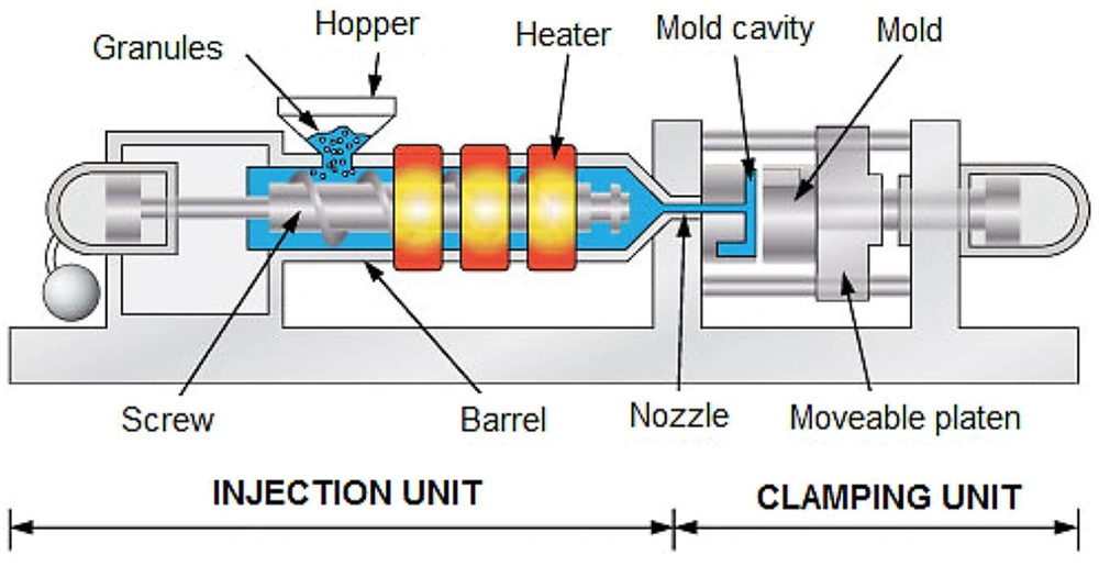
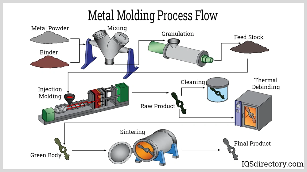
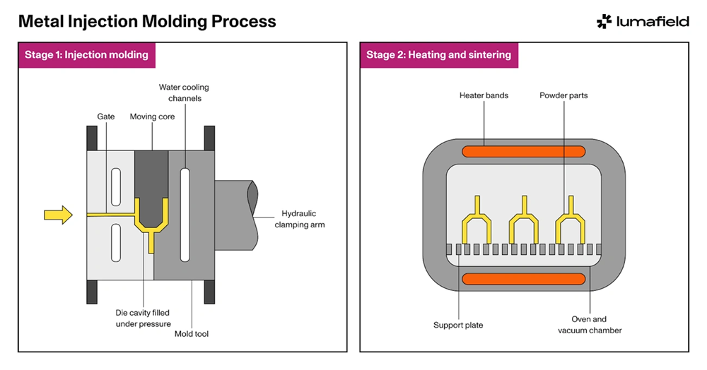
MIM’s process combines fine metal powders with a binder to create feedstock. Manufacturers inject this mixture into a mold, then debind and sinter it at high temperatures to achieve full density. The parts shrink by roughly 15-20%, and mold designers must factor this shrinkage into their designs. On top of that, certain thermoplastic resins that have lower flow rates, such as ABS and filled resins, tend to develop more knit line problems.
Small intricate metal components needed in medium to high volumes require manufacturers to prevent knit lines to maintain structural integrity. This piece explores proven strategies that minimize and eliminate knit lines in injection molding, especially when you have MIM components where precision and strength matter most.
Understanding Knit Lines in MIM
Knit lines pose the most important challenge in precision manufacturing. Understanding how they form and behave is vital to optimizing MIM component quality.
What are knit lines in injection molding?
Knit lines (sometimes called weld lines or mold lines) appear when separate flows of molten material meet but don’t fuse completely. These marks show up as faint lines, seams, or scratch-like marks on finished parts. They’re not just cosmetic flaws – knit lines create structural weak points that can reduce a component’s mechanical strength by up to 80% compared to its nominal strength. The appearance of these lines ranges from nearly invisible to marks that look like actual cracks, depending on material properties and processing conditions.
How knit lines form during the MIM process
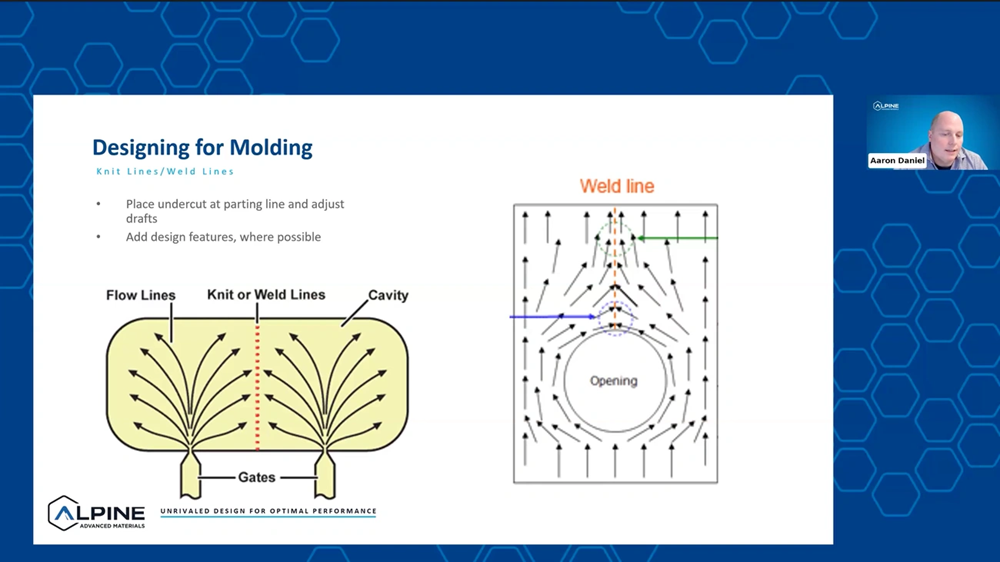
We observed knit lines form when molten material flows split and rejoin. This happens in three common scenarios:
- Material flows around obstructions like cores or inserts
- Flow fronts merge from multiple gates
- Features like holes, bosses, or complex geometries cause flow separation
The process involves “fountain flow” – molten material creates a skin of stationary material when it touches cooler mold surfaces. Two flow fronts create a V-shaped groove at their meeting point, which acts as a mechanical stress concentrator. Molecular entanglement becomes incomplete if the material cools too much before meeting, which leads to reduced strength.
Why are MIM components more prone to knit lines?
Metal Injection Molding components face unique challenges with knit lines. Here’s why MIM parts are especially susceptible:
- Complex geometries – Manufacturers choose MIM because it creates intricate metal parts with complex features, which increases the chances of flow front separation and rejoining.
- Flow length sensitivity – Long flow paths make knit lines more noticeable. Cylindrical MIM parts with central cores force material to travel further around obstructions before meeting on the opposite side.
- Material characteristics – MIM’s metal-polymer feedstock flows differently than pure thermoplastics. Metal particles make complete fusion harder once the material starts cooling.
- Fiber orientation issues – Filled materials, common in MIM, have fibers or particles that can’t cross-knit lines effectively. This creates weaker areas where flows meet.
- Temperature sensitivity – MIM requires precise temperature control, which makes it vulnerable to flow fronts cooling too early.
Design Principles to Minimize Knit Lines
Design principles are the foundations that help minimize knit lines in metal injection molded components. Smart strategies at the design stage will reduce structural weaknesses and cosmetic flaws by a lot.
Maintain uniform wall thickness
MIM components need uniform wall thickness to reduce molding process flaws and improve part quality and dimensional tolerances. Wall thickness should range from 1mm to 6mm (0.04″ to 0.25″), based on the component’s size. You should create gradual transitions between different thicknesses when variations can’t be avoided. Coring out thicker areas helps keep uniformity and saves expensive fine metal powder, which makes it more affordable.
Use filets and radii to improve flow
Filets and radii do more than just look good. They help create smoother material flow during injection and eliminate sharp corners that could crack or erode mold features. Well-designed filets spread stress evenly across parts, which reduces stress buildup that might cause part failure. The best results come from fillets and radii between 0.4mm and 0.8mm (0.015″ to 0.030″). Internal radii should be at least 0.5 times as thick as the adjacent wall.
Avoid sharp corners and abrupt transitions
Sharp corners concentrate stress, which makes parts more likely to fail and reduces their strength against impact. On top of that, they block molten material flow during injection, which might lead to incomplete filling. Parts should never have an edge radius smaller than 0.005″ to 0.006″. Smooth transitions between different thicknesses help spread material flow evenly, lower internal stress, and keep dimensions stable.
Optimize hole and slot placement
Holes and slots add functional features without extra cost and help reduce part mass while keeping wall thickness uniform. Holes that run perpendicular to the parting line are easier and cheaper to mold. However, parallel holes need mechanical slides or hydraulic cylinders that get pricey. You need to think about potential sealing-off problems and flashing issues when designing interconnected holes.
Design for balanced material flow
Balanced material flow creates uniform filling and cooling, which reduces warpage and improves dimensional stability. Features that cause knit lines should be placed away from part edges when possible. Holes and bosses near edges slow down resin the most. Thicker part walls let plastic flow more easily through the mold, but walls that are too thick might cause sink marks.
Gating and Flow Optimization
Gating strategy plays a critical role in reducing knit line formation. The selection and placement of gates can change how material flows and fuses within the mold cavity.
Choose the right gate type and location
Gate selection shapes part quality and manufacturability. MIM processing employs three main gate types: tab gates (most common and largest), hot tip gates (near part center), and pin gates (on non-cosmetic surfaces). Tab gates excel with glass-filled resins, while hot tip gates leave fewer vestige marks. Gates work best at the thickest cross-section, letting material flow from thick to thin sections. This reduces voids and sink marks. The placement also balances clamping forces and reduces dimensional issues.
Use multiple gates for complex parts
Complex MIM components need multiple gates to distribute material flow better. This strategy eliminates weak intersections through strategic plastic flow. Multiple-cavity tooling requires careful sizing and positioning of the gate and runner system. Each cavity must fill with similar amounts of feedstock at balanced rates.
Avoid long flow paths around cores
Material flowing through long paths around cores creates more knit lines. The material cools too much before meeting on the opposite side of obstacles. This creates visible and potentially weaker knit lines.
Control the knit line location through gate design
Smart mold design places knit lines in non-critical areas. Simulation tools help find the best gate locations that reduce knit lines on part fit and function. Dual gating in cylindrical parts with central cores can minimize or eliminate visible knit lines.
Material and Process Adjustments
Design plays a crucial role, but material selection and process optimization are the real game-changers in preventing knit lines. JH MIM brings nearly 20 years of expertise in the metal injection molding industry and understands these critical factors well.
Pick resins that flow better
The right material choice makes all the difference in knit line formation. Unfilled materials create stronger knit lines compared to filled materials. Knit line strength drops as filler content goes up. Pure copper powder works great for MIM applications. The powder should be spherical with an average particle size of 5.2 µm. Mix it with wax binder at a powder/binder ratio of 95:5 (mass%). On top of that, POM-based binders show promise. They flow exceptionally well through complex part geometries.
Fine-tune your injection speed and pressure
The way flow fronts meet and fuse depends on injection parameters. A higher injection pressure of about 5 MPa works best for certain copper MIM feedstocks. This helps distribute materials evenly. The fill speed should stay high to keep the flow front hot. This step matters a lot for good bonding at weld lines. But watch out – too much speed near the gates can lead to uneven powder concentration.
Keep an eye on the mold and melt temperature
Temperature control can make or break your process. Research shows hot molds boost knit line strength the most. High melt temperatures help too. The mold temperature should match the material’s crystallization temperature. The water flowing through mold channels needs careful monitoring. Temperature differences between entry and exit points should stay within 3-5°C. This helps maintain dimensional stability.
Let simulation tools spot knit lines early
Modern manufacturers use Moldflow and Moldex3D to spot potential knit line locations before production starts [24]. These smart tools track powder concentration, shear rate, and flow patterns. The simulation results match up well with actual molded parts. The Taguchi method works great with these simulations. Together, they help nail down the best MIM processing conditions.
Fix issues with post-processing
Black lines often show up during the original feedstock injection. These turn into visible defects after sintering. Sometimes, prevention isn’t enough, and the work needs fixing. Multiple gates with valve control can help knit lines look better. A good mechanical polish might be your best bet. This technique creates surfaces just as smooth as traditional methods.
Conclusion
Manufacturers face a crucial challenge when dealing with knit lines in metal injection molding. Companies can substantially reduce these structural weaknesses by applying the design principles we discussed. Strong finished parts need smooth material flow, which comes from uniform wall thickness, well-placed fillets and radii, and the absence of sharp corners.
Gate design and placement are the foundations of controlling material flow through complex mold cavities. The structural integrity of MIM components improves with the right material choice and precise processing parameters, especially when you have proper temperature control. Modern simulation tools give manufacturers the ability to spot potential knit line problems before starting production.
Success with knit lines demands a complete approach that combines smart design, effective processing, and deep material knowledge. JH MIM brings nearly 20 years of expertise in Metal injection molding and Powder metallurgy. Our factories span over 18000 square meters with world-class equipment. Our 150 skilled workers deliver precision-engineered products to customers worldwide.
The key to preventing knit lines lies in understanding how they form. These defects aren’t inevitable. Manufacturers who follow these best practices create stronger, better-looking components consistently. Investment in knit line prevention leads to improved product performance, fewer rejections, and happier customers.
Key Takeaways
Master these essential strategies to eliminate knit lines and produce stronger, higher-quality MIM components with improved structural integrity and reduced defect rates.
• Design for uniform flow: Maintain consistent wall thickness (1-6mm), use filets/radii (0.4-0.8mm), and avoid sharp corners to ensure smooth material flow and prevent weak fusion points.
• Optimize gate placement strategically: Position gates at thickest sections and use multiple gates for complex parts to control knit line location and minimize their impact on critical areas.
• Control temperature precisely: Hot molds and elevated melt temperatures significantly improve knit line strength – maintain mold water temperature differences within 3-5°C for dimensional stability.
• Leverage simulation tools: Use Moldflow or Moldex3D software to predict knit line locations before production, enabling proactive design adjustments and optimal processing conditions.
• Select materials wisely: Choose feedstocks with better flow characteristics and proper powder/binder ratios (95:5 mass%) to reduce knit line severity and improve overall part quality.
Preventing knit lines requires a comprehensive approach combining thoughtful design, strategic processing, and material expertise. Companies that implement these best practices can reduce knit line-related strength losses (which can reach 80% of nominal strength) while achieving consistent quality and enhanced product performance.
FAQs
Q1. What are the main causes of knit lines in injection molding? Knit lines typically form when separate flows of molten material meet but fail to fuse completely. This often occurs around obstacles like cores or inserts, when flow fronts merge from multiple gates, or around features like holes and bosses in complex geometries.
Q2. How can I minimize knit lines through part design? To minimize knit lines, maintain uniform wall thickness (1-6mm), use filets and radii (0.4-0.8mm), avoid sharp corners, and optimize hole and slot placement. Also, design for balanced material flow by placing knit line-causing features away from part edges when possible.
Q3. What role does gate design play in preventing knit lines? Gate design is crucial in minimizing knit lines. Choose the right gate type and location, preferably at the thickest cross-section. For complex parts, use multiple gates to distribute material flow more effectively. Strategic gate placement can help control knit line location and reduce their impact on critical areas.
Q4. How do processing parameters affect knit line formation? Processing parameters significantly influence knit line formation. Increasing injection speed and pressure helps maintain a hot flow front for better bonding. Controlling mold and melt temperatures is critical, with hot molds and elevated melt temperatures improving knit line strength. Aim to keep mold water temperature differences within 3-5°C for dimensional stability.
Q5. Are there any post-processing techniques to address knit lines? While prevention is ideal, some post-processing techniques can help address knit lines. Valve gate control, especially with multiple gates, can improve knit line appearance. Mechanical polishing techniques can also be used to achieve smoother surfaces and potentially reduce the visibility of knit lines.