MIM Design Guide
Metal Injection Molding is a metal part that follows a similar approach to plastic injection molding, allowing the product to have both the design freedom of plastic injection molding and the characteristics of a metal forging process, thus providing a great deal of flexibility in design for iron-based, stainless steel, titanium, ceramics, and other materials to produce virtually any geometry without limitation. the MIM process allows for complexity, miniaturization, high precision, and multi-part combinations.
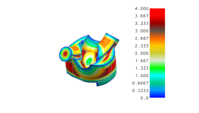
The MIM Design Guide is designed to evaluate the mold design of MIM products, design typing lines, gates, inject marks, etc., and assess the feasibility of product production through mold flow design software:
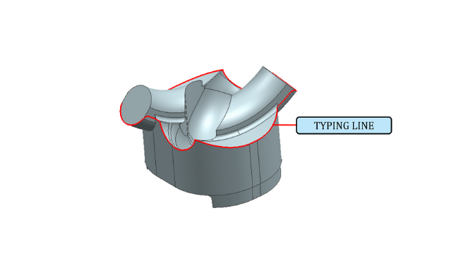
Design typing lines
Each MIM part has a parting line from which the two mold halves converge to form a cavity. However, more creative designs can hide the typing line on the product. Design parting lines along the edges of the featured product and make the sort lines less visible.


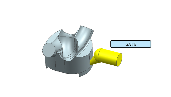
Gates
Gates are the cavities where the MIM material is injected. Depending on the product structure, I have four most common gate designs: tab, tunnel, jump, and drop. This placement is very complex. Typically, the gate placement sets the material into the part area with the largest cross-section, from thick to thin-filled parts. For example, on cylindrical parts, gates are positioned as close to the center axis as possible to prevent sintering distortion.
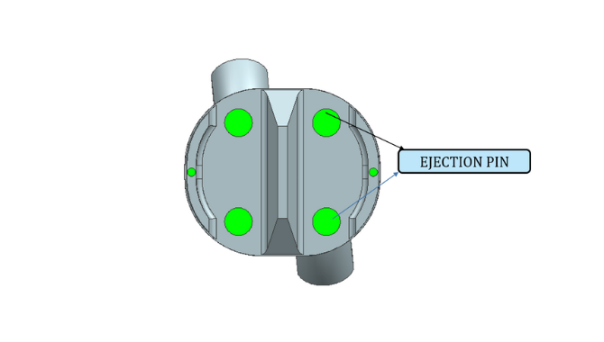
Ejector pin
The ejector pin is used to eject the part from the mold cavity. This is because the ejector pin leaves a witness mark on the part. So these marks are placed where they are not visible during the part assembly process or reduced by later polishing.


Cam
An undercut is formed on the part without a secondary operation. When designing parts with undercuts, keep in mind the direction in which the cam must move to form the undercut.

