
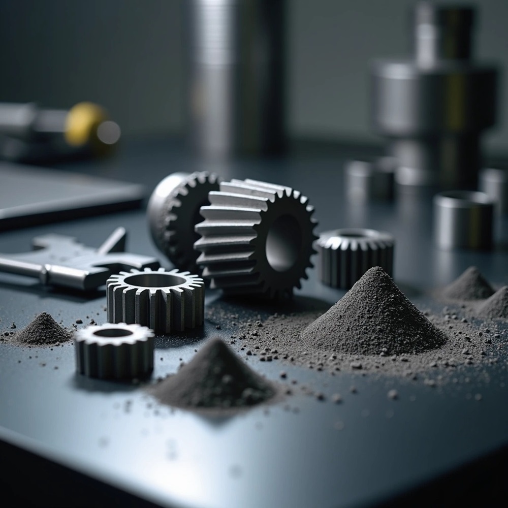
Powder metal parts exhibit distinct mechanical characteristics shaped by their inherent porosity and manufacturing methodology. The powder metal sintering process produces components with strength levels that engineers can predict and control through density management and post-processing treatments.
Ferrous powder metallurgy materials processed through standard die press and sinter routes deliver ultimate tensile strength (UTS) levels up to around 900 N/mm² in the as-sintered condition. Heat treatment or sinter hardening extends this capability to around 1,200 N/mm². Tensile yield stress reaches up to 480 N/mm² as-sintered and climbs to 1,200 N/mm² after heat treatment. Compressive yield stresses run higher at 510 N/mm² in the sintered state or up to 1,250 N/mm² when heat treated.
These strength values come with a trade-off. Elongation levels fall below 2%, which reflects the low tensile ductility characteristic of sintered powder metal parts. Then conventional press and sinter density levels that reach a maximum of 7.1-7.2 g/cm³ make these components unsuitable for applications that experience gross plasticity during service.
Fatigue performance demonstrates respectable endurance limits. Press/sinter PM steels achieve up to 320 N/mm² in rotating bend loading mode as-sintered, while axial loading mode yields 270 N/mm² (R = -1, Kt = 1). Heat treatment raises these values to around 540 N/mm² and 460 N/mm².
Density remains the dominant factor that influences strength, ductility and hardness. Dynamic characteristics such as impact energy and fatigue limit improve sharply at densities exceeding 7.2 g/cm³. Wrought materials outperform standard sintered components in absolute strength, but powder metallurgy parts show reduced sensitivity to notching geometries.
Core Mechanical Properties of Powder Metal Parts
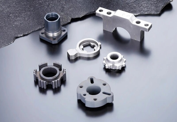
Engineers selecting powder metallurgy parts must review four critical mechanical properties that define component performance in a variety of loading conditions. Each property responds differently to the inherent porosity within sintered structures. Material selection becomes a balance between what the application needs and what manufacturing can deliver.
Tensile & Yield Strength: Load-Bearing Capacity under High Stresses
Load-bearing applications need engineers to assess both ultimate tensile strength and yield points. The powder metal sintering process creates components where strength relates directly to final density. Parts designed for static structural loads perform well within their yield limits. Engineers must account for the reduced safety margins compared to wrought equivalents. Then designers often specify higher density grades or post-sintering treatments when stress concentrations approach critical thresholds.
Fatigue Strength under Cyclic Loading: Overcoming Micro-Porosity
Cyclic loading introduces unique challenges for sintered powder metal parts. Micro-porosity acts as stress concentration sites where fatigue cracks start under repeated loading cycles. Engineers designing rotating shafts or gears must think about endurance limits specific to the powder metallurgy part’s density. Secondary operations such as surface densification or infiltration improve fatigue resistance substantially. They reduce surface porosity where crack initiation occurs most often.
Impact Resistance for Heavy-Duty Applications and Elongation Ductility
Heavy-duty applications that need impact absorption call for careful material selection. Standard sintered components have low ductility that limits energy absorption during shock loading. Engineers specify copper infiltration or achieve densities exceeding 7.2 g/cm³ when impact resistance becomes critical to component survival.
Wear Resistance and Tribological Performance in High-Friction Environments
Tribological applications benefit from the self-lubricating properties that controlled porosity provides. Oil-impregnated bearings and wear-resistant surfaces exploit interconnected pore networks to retain lubricants. Engineers designing sliding contact surfaces balance density requirements against the functional advantage of porosity to reduce friction in high-contact applications.
Sintered Material Standard Reference Portfolio (MPIF Grades)
The Metal Powder Industries Federation publishes MPIF Standard 35, which defines compositional ranges and minimum mechanical properties for structural powder metallurgy parts. This standardized reference system allows designers to specify materials with confidence among suppliers of all types.
The material designation code communicates both composition and strength. The prefix letters denote alloying elements. Numeric digits indicate percentages of major constituents and combined carbon content. The suffix number represents minimum ultimate tensile strength in thousands of psi. To name just one example, FC-0208-50 identifies an iron-copper material with 2% copper, 0.8% carbon, and 50 ksi (345 MPa) minimum tensile strength.
Mechanical Property Matrix for Common MPIF Material Grades (FC-0208, FL-4405)
| MPIF Material Grade | Sintered Density (g/cm3) | Key Mechanical Properties & Strengths | Typical Target Applications |
|
FC-0208-50
(Iron-Copper) |
$6.7 – 7.1$ |
• Tensile Strength: ≈ 340-380 MPa
• Hardness: ≈ 73 HRB |
High-torque structural joints, timing gears, sprockets. |
|
FL-4405-40
(Prealloyed Steel) |
≥6.7$ |
• Tensile Strength: ≈ 360 MPa
• Yield Strength: Optimized via heat treatment |
Heavy-duty transmission gears, automotive engine parts. |
| Custom High-Density Matrix | 7.2$ – 7.5$ | • Tensile Strength: Up to 900 – 1200 MPa (Post-treated) | Humanoid robot joints, aerospace components, high-load drive systems. |
FC-0208 copper steel delivers good sintered strength and dimensional stability for structural gears and hubs. FL-4405 prealloyed low-alloy steel offers superior hardenability and consistency during heat treatment. Heat treatment (quench and temper) boosts tensile strength by a lot in both grades.
How the Powder Metal Sintering Process Affects Properties
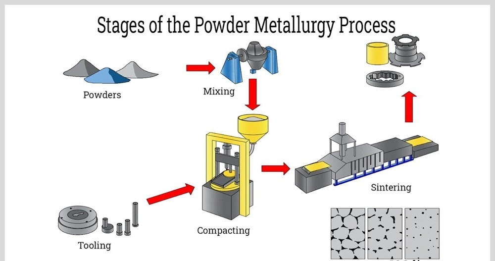
Process variables during the powder metal sintering process determine final part characteristics with precision. Material selection, pressing parameters, thermal treatment and cooling protocols each contribute distinct influences on mechanical performance.
Metal Powder Characteristics and Particle Size Distribution
Particle size distribution affects flowability, packing density and compaction behavior. Traditional powder metallurgy employs powders ranging from 0-150μm. The D50 median particle size defines the central distribution point. D10 and D90 characterize fine and coarse ends respectively. Smaller particles increase packing density but reduce flowability. Spherical particle morphology improves both flow characteristics and compaction efficiency. Inter-particle friction determines how powders fill die cavities and is measured through angle of repose testing.
Compaction Pressure, Green Density, and 1,000-Ton Presses
Compaction pressure generates green density through plastic deformation at particle contact zones. Conventional pressing reaches 600-800 MPa maximum due to technical and economic constraints. High-tonnage equipment achieves green densities approaching 7.1-7.2 g/cm³ and includes 1,000-ton hydraulic presses. Warm compaction at elevated temperatures delivers density increases of 0.07-0.15 g/cm³ compared to room temperature pressing. Advanced facilities operate servo-hybrid presses up to 5,000 tons for large-format components.
Sintering Temperature, Protective Atmosphere, and Grain Bonding Quality
The base metal’s melting temperature determines sintering conditions, which occur at 60-70% of that threshold. Iron-based materials sinter between 1100-1300°C. Protective atmospheres prevent oxidation and enable particle bonding through surface diffusion, grain boundary diffusion and volume diffusion mechanisms. Nitrogen-hydrogen atmospheres below 5% H2 content produce uniform microstructures with minimal decarburization. Atmosphere composition controls carbon potential and prevents surface contamination.
Cooling Rate and Metallurgical Microstructure Formation
Cooling rate determines phase transformation and final microstructure. Sinter-hardening processes employ accelerated cooling at 2.5-5°C/s to form martensite and achieve 32-37 HRC hardness. Slower cooling rates below 1.5°C/s produce bainitic structures with reduced strength. Controlled cooling preserves dimensional stability and relieves thermal stresses developed during sintering.
Advanced Post-Sintering Enhancement Methods
Secondary densification operations take powder metallurgy part performance beyond conventional sintering limits. Engineers specify these treatments when standard sintered density proves insufficient for demanding mechanical requirements.
Repressing and Resintering for Near-Theoretical High Density
Sizing involves secondary pressing of sintered components to control dimensions while increasing density. Repressing lifts density from 6.79 g/cm³ to between 7.08 and 7.45 g/cm³ at repressing pressures of 414 MPa and 827 MPa for Fe-2Ni-0.8Mo-0.5C components. Double-press-double-sinter adds another sintering cycle after repressing to reach final characteristics.
Warm Compaction at 120-150°C to Maximize Original Green Strength
Warm compaction heats powder and tooling to 120-150°C before applying pressure. Softening lubricants migrate to die surfaces faster and permit particle rearrangement. This method achieves 7.2-7.5 g/cm³ after sintering. Green strength exceeds 13 MPa (2000 psi) and removes green cracks in most geometries.
Metallurgical Heat Treatment: Carburizing and Sinter-Hardening
Carburizing diffuses carbon atoms into component surfaces in carbon-rich environments and forms hard carbides. Surface hardness reaches HRC 58-65 after quenching. Sinter-hardening combines sintering and hardening through accelerated cooling. The microstructure transforms into martensite without separate quenching operations. This process cuts energy consumption by 60% and removes heat treating steps.
Copper Infiltration for Void Elimination and Maximum Impact Resistanc
Molten copper drawn into pores through capillary action increases density to about 7.3-7.5 g/cm³. A 15% copper infiltrant amount produces surface hardness of HRC31, impact energy of 31.34 J and tensile strength of 759 MPa. Bottom infiltration provides 15.41% higher impact energy compared to top infiltration at 12.5% copper content.
Vacuum Resin & Oil Impregnation for Corrosion Protection
Vacuum resin impregnation fills pores with thermoset polymers and seals leak paths permanently. The process provides pressure tightness and corrosion resistance up to 400°C. Oil impregnation makes self-lubricating bearings that absorb 10-30% oil by volume. Wet vacuum methods use atmospheric pressure to fill porosities, while dry vacuum prevents degassing disruption.
JHMIM brings over 20 years of deep expertise in powder metallurgy and metal injection molding (MIM). We operate a state-of-the-art 18,000+ square meter manufacturing facility in China. Our team of 150+ skilled technicians and advanced high-tonnage sintering and pressing equipment deliver high-density, zero-defect complex metal components globally. We streamline your supply chain and solve tight-tolerance manufacturing challenges under one roof.
Engineering Considerations for Powder Metallurgy Part Selection
Part selection decisions require engineers to review multiple interdependent variables that determine whether the powder metal process delivers optimal results for specific applications.
Density Requirements: Achieving the 7.2 to 7.5 g/cm³ High-Performance Range
Designers targeting high-performance applications specify densities between 7.2 to 7.5 g/cm³ where dynamic properties approach wrought material equivalents. Standard pressing reaches 7.1-7.2 g/cm³. Warm compaction or infiltration achieves the upper range. Applications with shock loads or high fatigue cycles just need these elevated density levels.
Material Matrix Selection: Ferrous vs. Non-Ferrous Powders
Ferrous powder metallurgy dominates structural applications due to cost efficiency and heat treatment response. Non-ferrous alternatives such as copper, bronze, or stainless steel address specific requirements like corrosion resistance or electrical conductivity.
Geometry & Design Limitations: Wall Thickness, Radii, and Slopes
The powder metal sintering process imposes geometric constraints. Uniform wall sections ensure consistent density distribution during compaction. Sharp internal corners and thin walls below minimum thresholds create pressing challenges. Tapers and slopes must arrange with tooling withdrawal directions.
Cost-Performance Trade-offs: Traditional Machining vs. Net-Shape PM
Net-shape powder metallurgy part production eliminates secondary machining for high-volume runs. Setup costs exceed traditional machining at first, but per-piece economics favor powder metal above 10,000-unit production volumes.
Partner with JHMIM for High-Strength Sintered Components
Translating component stress requirements into high-performance sintered parts requires collaboration between design engineers and powder metallurgy specialists. JHMIM streamlines this review process by accepting CAD files at the concept stage. This provides early design-for-manufacturing feedback before finalizing part designs.
Submit Your Component Stress Requirements and 3D Drawings (STEP/IGS) for a Free Material Review
Engineers submit 3D models in STEP or IGES format with 2D drawings specifying critical dimensions and tolerances. STEP files store 3D image data in ASCII format following ISO 10303-21 standards. IGES defines a vendor-neutral data format and allows digital exchange among different CAD systems. These formats ensure compatibility whatever CAD software the design team uses.
Annual production volume estimates should accompany submissions with functional requirements such as strength and hardness specifications and cost targets to review feasibility. The engineering team reviews component geometry by analyzing surface area, wall thickness, material properties, compaction ratios, required density levels and secondary operations. This review identifies opportunities to improve manufacturability while maintaining performance objectives.
Multi-disciplined engineers create solid models adjusted for dimensional changes during the powder metal sintering process. They build parametric press stack-ups to visualize tooling and generate individual tool drawings with materials, tolerances and finishes specified. The team recommends optimal powder blends delivering required mechanical properties for specific applications.
FAQs
Q1. What tensile strength can powder metal parts achieve? Standard powder metal parts reach ultimate tensile strength up to approximately 900 N/mm² in as-sintered condition. With heat treatment or sinter hardening, this can be extended to around 1,200 N/mm². The strength levels depend primarily on the final density achieved during manufacturing and any post-processing treatments applied.
Q2. Why do powder metal components have low elongation compared to wrought materials? Powder metal parts typically exhibit elongation levels below 2% due to their inherent porosity. The micro-pores within the sintered structure limit tensile ductility, making these components unsuitable for applications requiring significant plastic deformation during service. Standard press and sinter processes reach maximum densities of 7.1-7.2 g/cm³, which contributes to this reduced ductility.
Q3. At what density do powder metal parts show significant improvement in dynamic properties? Dynamic characteristics such as impact energy and fatigue limit improve sharply when densities exceed 7.2 g/cm³. This high-performance range of 7.2 to 7.5 g/cm³ brings powder metal components closer to wrought material performance levels. Achieving these densities typically requires advanced techniques like warm compaction, copper infiltration, or repressing and resintering.
Q4. How does the MPIF material designation system work? The MPIF designation code communicates composition and strength in a standardized format. Prefix letters indicate alloying elements, numeric digits show percentages of major constituents and carbon content, while the suffix number represents minimum ultimate tensile strength in thousands of psi. For example, FC-0208-50 indicates iron-copper with 2% copper, 0.8% carbon, and 50 ksi minimum tensile strength.
Q5. What secondary processes can enhance powder metal part performance? Several post-sintering treatments boost mechanical properties beyond standard sintering limits. Repressing and resintering increase density to near-theoretical levels, while copper infiltration eliminates voids and maximizes impact resistance. Heat treatments like carburizing achieve surface hardness of HRC 58-65, and sinter-hardening combines sintering with accelerated cooling to form martensite without separate quenching operations.